Welcome
EazyCNC

jDraft 2.0


PureJavaComm
PIC CDC ACM
Weather
Ten-Buck Furnace
H8S Bootloader
Camera Calibration
Multitouch
Myford VFD
Fun with HC08
bl08

printf II

Java Goes Native
Densitometer
printf

jApp

Igloo

New Furnace

New Furnace
Part II

Linux 101

H8S/gcc
Quickie
Gas Fired Furnace
Down Memory Lane
Exlibris
Wheel Patterns
Glitches
CHIP-8
eDice

Animato

jDraft
JNA Benchmark
Contact Info
Making of the Wheel Patterns
Introduction
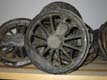
To me the wheels and the wheel arrangement are one of the most characteristic and interesting features of an engine. In the prototypes these were invariably (I guess) made of cast steel. For me that is the only way to go in a model too. Of course in a back yard foundry one has to do with cast iron. The wheels are probably the most visually prominent part of an engine. They also have the most complex geometry of all the castings in an engine, therefore I felt that a method that would be easy and sure to execute by a complete novice like me was called for. Or to tell you the truth, I just enjoyed thinking and playing with the ideas of various methods and this is the story of how I did it. I don't know if this method has any novelty and I let the reader to decide wether my method has any merit.
To quote Terry Aspin "the making of full-size patterns for locomotive wheels represents an example of very fine carpentry". In his book he outlines two methods of making the patterns, either carving them out of solid wood or building them up on a back plate from turned rim and center and jig filed spokes. Neither of these realy appealed to me, the former requiring too much experience and skill and the later, while described as "wheels without tears", still seemed too time consuming (in terms of time spent in the shop) and yet leaves too much (to me liking) room for hand craft. Especially I felt that where the spokes meet the counter weight and where the driving pin center joins the hub too much would depend of my skill and therefore chance. In retrospect I think I was right in terms of precision achieved and time spent in the workshop, unless I count in all the mistakes I made or the time spent in planning. But for me this is the fun part and thinking is something that you can do while driving to/from home or having a bath, whereas jig filing requires that I spend time in the shop away from my homely duties.
The Starting Point
The "Litle Jumbo" I'm building is a 2-8-0 with a 6 wheel tender so a total minimum of 4 different patterns are required. Un-luckily the counter weights in my prototype loco are assymetrical necessiating mirrored patterns, one for each side of the wheel. Otherwise I could have got away with less patterns. From the outset I had litle doubt (against advice from literature and friends) that I wanted to have two sided patterns. After inspecting some real models and experimenting with preparing the sand moulds I feel I was right even if this meant that 6 different patterns were required. With the kind of slender spokes and rim that the prototype has I think that the difference between one sided and two side castings is clearly visible. With some prototypes this is not the case. Also the succesfull withdrawall of the pattern becomes harder as the thickness of the pattern increases. A two sided back plated pattern is realy a lot easier to withdraw cleanly than a twice as deep loose wheel pattern.
The Idea
The idea I had on how to make the patterns was to machine out a mould of the pattern in a 'negative' form and then cast the actual pattern from epoxy resin. For the material I used "synthetic wood" (brand name "Cibatool"). If you consider it for a second it is obvious that with form cuttin tools and a rotary table almost all features of the wheel geometry can be trivially produced in a negative form on a milling machine (look dad, no CNC). The rim and the center hub are totally trivial. By tilting the rotary table a litle the spokes are easily given the kind of tapering required. By off-setting the the center of rotation the driving pin hub and counter balance are easy easily machined and even the concave archs that join the two hubs are easily produced, a thing that would have to be built up from a filler material and hand formed if a positive pattern were to be built up. After machining litle skill is required to round of the corners where the spokes meeth the hubs and rim.
The Implementation
Drawings
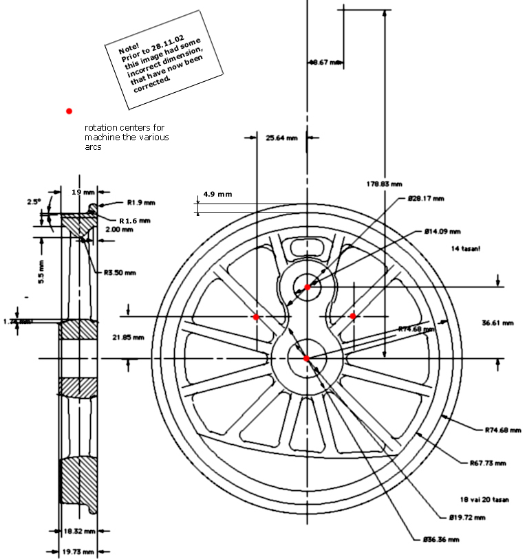
First I needed some drawings of course. This involved a lot of
measurements from photos and from one of the surviving prototypes that
is rusting away on a side railing in Helsinki Pasila. The wheel profile
is copied from the Golden Gate Live Steamers web-site and conforms, I
hope, to the Brotherhood of Live Steamers standard for 7 1/4" gauge
too. (Prior to 28.11.02 it didn't, I hope it does now. Take care.)
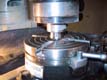
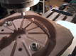
The Tools

As illustrated above four form tools were used to cut the rim,
spokes and hubs for the pattern mould. One tool is simply a tapered (to
5 deg draught angle) bit. This was used to cut the rim of the wheel.
The rim part could also have be turned but this wheel is at the limit
of what can be turned in a Myford ML7 so there was no way to I could
turn the mould for wheel pattern in it! Anyway, milling it was probably
faster and more accurate. A half elliptical tool was used to mill the
spokes. To get the proper narrowing of the spokes the rotary table was
tilted about 5:150 for that operation (by placing a 5 mm dia rod under
one end). A half barrel shaped tool was used to form the hubs and the
inside arc of the counter weight. And a rounded off triangular tool was
used to machine that part of the wheel that in the prototype is the
actual wheel on which the tyre is attached.
The tools were turned from bright mild steel and machined to D-bits.
The Cibatool material machines easily, so no hardening of the tools was
necessary.
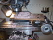
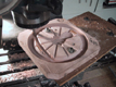
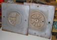
Means of locating
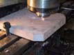
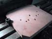
The pictures above illustrate how the various centers of rotation were located during machining. The idea is to align the center of the rotary table with the axel of the milling machine. This is done by using a M2 manderel that ends in a 10 mm dia section with a 10 mm collet in the milling machine. By raising the milling table the rotary table, which must be loose at this stage, automatically centers itself on the table. Then the bolts are tightened up. After that it is easy to offset the rotarytable with the index wheels to cut any desired radius with the form tools. Inside and outside arcs are easy to produce accurately.
Cutting It

At this setup machining the mould to reasonable accuracy with the form tools was childs play, even I could do it!
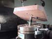
Offset Required
It is amazing how easy it is to over reach the capacity of your tools....The counter weight cavity was cut by shifting the center of the rotary table quite a lot and then the cavity was cut using the same form tool as was used for the hubs. Two (or actually four, because I wanted something to fall back on if necessary) patterns for the coupled wheels were cast on these pattern moulds and then the counter weight cavities were enlargened to the driving wheel size. In my loco the counter weight on the driving wheel is considerably larger than on the coupled wheels. A litle bit of support by hand was necessary to damp the (not so good) vibrations during machining. The vibrations were in the vertical direction and thus did not realy matter as the affected surface of the counter weight on the final casting will be machine anyway, but it irritated the operator (that's me).
(NB: When cutting for the counter weight as above it is necessary to overlap the rim and the counter weight area to some extent. Unless the vertical depth of the cutter exactly mathes the depth of the rim and there is no vibration then the rim is bound to be too thick at places around the counter weight. This per-se does not matter, as the rim will be turned anyway. However this extra thickness makes it harder to chuck the final casting so that the plane of the wheel is parallel to the chuck jaws. This could have been easily avoided if I had turned the face of the epoxy resin patterns (see below) after they had been cast.
Reinforcements Arrive
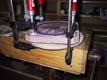
Some experimenting was necessary to find out a method that works for casting the patterns succesfully. My original plan was to produce just one 'mother of all wheels' from the first mould (the grandma, I guess) without the counter weight. Then this 'mother' would have been used to produce four negative 'daughters' on which the counter weights could have been milled. I wasted quite a lot of time on experimenting with this. I tried to produce the daughters in plaster of paris but I just could not reliably withdraw the mother. I actually distroyed one or two 'moms' in the process. Some kind of castable plastic material would probably have done the trick but I did not have them at hand. I now know some compaunds that behave, after curing, like the Sibatool synthetic woods. They probably would have worked. In the end I did as described here and just produced four 'moms' by machining. Well, some you win, some you lose...
I also lost one 'mom' and the associated 'grandma' by not being able to withdraw it from the mould. After that I came up with the push out pin idea (nothing original about that, I just had to learn it the hardway).
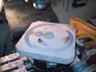
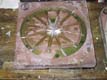
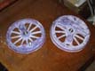
Plates and Left Overs
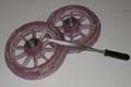

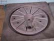
After casting in epoxy resin the back sides of the half patterns were cleaned up in the lathe and bolted together through two holes that ensure the allignment of the halfs. A litle bit of filing was necessary to ensure that the spokes matched at the parting line/plane. Finaly the half patterns were glued to a ply wood plate, again using the bolts to ensure alignment. (BTW: I prefer plate patters, no playing around with parting sand and the associated yet-an-other-chance of bungling up the job). Some filling up with epoxy putty was necessary to make sure that the sand cannot get between the pattern and the plate as this tends to brake off some sand when withdrawing the pattern, and we don't want that, do we?
The patterns for the big wheels were produced more than a year ago, but I just finished producing two patterns for the bogie and tender wheels and it took me only some hours to do that to a good accuracy so I think this method has some merit. And the castings don't look too bad considering...
Kusti 23.11.2002