|
|
Drawing aids is, in a way, what jDraft and 2D CAD is all about, to be able to draw accurately and with ease.
Accurately here means with precision.
When you draw shapes, lines, arcs, anything, you are not limited to the accuracy of how well you can point with the mouse or see what you are drawing on the screen. Instead when you draw e.g. a line from point to point, you pick the point on something that is already defined in the drawing, say the end point of another line, the crossing of two lines or from a grid. Or you define it by constraints, saying that the line is to be a tangent to a circle and passing through a point. Precisely, perfectly.
In the end, the drawing is probably printed on a paper with a printer having a resolution of about 300 DPI (5 lp/mm) so why this craving for accuracy?
To understand this, consider that in a drawing made at 1 : 100 scale the above mentioned printer resolution results in an accuracy of about 0.1 mm which would mean that any Dimensioning would have a precision of about 10 mm! Clearly not acceptable. And things would get even worse as things are copied and pasted as the accuracy would deteriorate every time.
Hence the need to draw precisely.
Of course, nothing is perfect and for the technically inclined the accuracy is limited by IEEE double precision floating point math and is aproximately sixteen significant digits. Note that some geometrically almost singular cases can affect the accuracy of the math jDraft performs, such as intersection of tangential lines and circles or almost parallel lines. Also, the mathematics related to splines and ellipsoids are not always as precise because they rely on numerical rather than analytical models and thus things like intersections of splines and ellipsoids may not be as accurate as intersections of, say, lines and circles.
Whenever you are drawing, the cursor turns into a cross hair. In addition to this cross hair that moves as you move the mouse, there is a Snap Cursor, figure 8.1 that tracks the point that would/will be entered if you click with the mouse. This snap cursor gives clear visual indication of what the cross hair cursor is snapping to.
|
|
Sometimes seeing the snap cursor is not enough. Consider a situation where two lines start from almost, but not quite, the same point. In order to draw precisely it is important to see which one is snapping the cursor. To help visualize this, the shape(s) snapped to are Hilited with a hilite color (orange by default, but you can change it in the preferences dialogue).
The above introduction covers the fundamentals of snapping to shapes.
In short, all you have to do is to select the snap mode and point and click at the shape you want to snap to. The snap cursor and the hilite indicate to you what you are doing. Figure 8.2 shows most of the shapes with their Handles which are also their snap-points. Note that sometimes the snap cursor and what you are pointing to with the cross hair cursor can be wide apart on the screen, for example when you are snapping to a center of a circle you point the circle circumference with the cross hair but the snap cursor will appear at the center of the circle.
|
|
Often there are two or more points into which the cursor could snap to, like two end points of a line. In situations like that, the software selects the closest one and thus you can affect what the software picks (in case it is not what you want) by moving the cursor to a different point.
You select the snap mode in effect using the Snap -toolbar in figure 8.3.
|
|
Snapping can be restricted to shapes on the current layer (as opposed to all visible layers) and to all visible shapes, shapes that are lower in the groups hierarchy (in other words shapes that are sub-groups of current group) or only to the current group. You control this with the Snap Controls -toolbar in figure 8.4.
|
|
A Grid is a rectangular array of points that are spaced at equal distance from each other. When you snap to a Grid the nearest grid point is picked. This makes it easy to draw things to conform to some, well, grid. Any number of grids can be defined, but only one of them can be active at any time. Grids have names and colors to distinguish them on the screen and lists.
The Active grid is displayed, and can be changed with, the Select Grid -drop down menu on the top toolbar.
Figure 8.5 shows the grid setup dialogue which you can bring up from the Settings/Grids... -menu command.
|
|
Each grid has the following properties
Spacing determines the distance between grid points.
Color is the color used to display the grid on the screen. When a grid is active, it is displayed as a rectanglular array of tiny dots behing all layers.
Ticks specify how dense the displayed grid/dot array is. A value of one causes each grid point to be displayed, a value of five shows every fifth grid point only. Note that in order not to fill the screen with dots when the grid is dense or when the view is zoomed out, the sofware selectively displays even fewer points than specified by the Tick property.
Snapping however always takes place at the Spacing resolution, regardless of the display grid points.
Guide lines come in two varieties, lines and circles. You create guide lines with the tools in the Guide -toolbar, see figure 8.6 and figure 8.7.
|
|
|
|
They behave mostly as normal lines and circles, you can move them, copy them etc. They are on a layer, obey the layer visibility and color and so on. But most importantly, you can snap to them. That is what they are for.
They differ from ordinary lines and circles in three respects.
The Guide Lines Style has by default width of zero which makes a guide line always to appear as one pixel wide regardless of the zooming. You can edit the Guide Line Style as any regular line style by bringing up the Line Style -dialogue with the ’Settings/Line Styles... -menu command.
Reference Points are small markers that you can make. Like guide lines, they are not printable. Reference Points have no size, so they appear the same regardless of zooming. This is mostly handy but can be annoying when zooming ’all out’.
|
|
A large number of reference points is usually a pain when drawing.Therefore Reference Points come in two varieties, permanent and temporary. Permanent Reference Points are like any other shapes, they exist until you explicitly delete them.
Temporary reference points, on the other hand, are consumed as you draw snapping in to them. After all, once you draw a line snapping to a Reference Point, the Reference Point is superfluous because now you can snap to the end of that line when necessary.
By default all reference points are borne temporary. Guide Lines and Reference Points both reside on some layer. By default they are created on the current layer. However, you can specify that they are created on a specific layer regardless of the current layer.
To change these settings, double-click on the Reference Point button in the Guide palette to bring up the Guide Parameters -dialogue, see figure 8.9.
|
|
You create Reference Points with the tools in the Guide -toolbar, see figure 8.10.
|
|
All shapes have snap points to which you can snap. Most of them are intuitively placed and obvious, like end points and center points. Mostly these are in the same locations where the Handles appear on selected objects. However, there are some exceptions that you may want to know of.
Circles have four handles that are at 90 degrees apart on the circumference. These handles are wherever you drag them. In addition, these circles have four ’quarter points’ that are also 90 degrees apart but are aligned with the current coordinate system, as illustrated in figure 8.11. You can snap to all of these.
|
|
Line ends and vertexes for polylines are snap and handle locations. Line centers and line segment centers for polylines are snap points, in snap to center mode, although there are no handles there.
Every text block has an anchor point. The text layout is defined relative to this anchor point, which also serves as both the handle and the snap-to location
Sometimes, especially when you are snapping to the crossing of two shapes, there are more than two shapes so that it is impossible to point with the cursor so that exactly the two shapes that you want are picked. You can see from the Hilite that the wrong two shapes are being picked, but no matter how you move the cursor or zoom the display you just can’t pick the right ones. This is surprisingly common with horizontal/vertical lines drawn on top of each other. The sofware has built in heuristics to reject parallel line cases, but sometimes that is not enough.
In situations like that you use the TAB -key to cycle through all possible combinations of shapes that could be picked up given the mouse location. Just keep pressing the TAB -key until the shape(s) you want are hilited.
Many people seem to think that CAD drawing involves a lot of coordinate systems and arithmetic and find them a turn-off.
Actually, coordinate system are not that central in drawing precisely. There are a few things about coordinate systems you’ll want to understand.
Coordinate systems have names for your convenience. No two coordinate system can have the same name. There can be any number of coordinate systems on a drawing but only one of them can be active or current at the same time.
The current coordinate system is the one used when entering or displaying numerical values to/from the drawing. It defines the scale of things when you draw, enter values, measure sizes or dimension parts. That is the most important thing to understand about coordinate systems. On the screen, the current coordinate system origin is visualized as in figure 8.12
|
|
Changing the coordinate system changes nothing in the drawing, it just changes the interpretation of what you enter or what the software displays. Internally, a 10 mm line is always a 10 mm line in a given location in the internal, fixed coordinate system of the document.
Note that the units used in entering numerical values or displaying coordinates do not come from the settings of the coordinate system but are set in the Settings/Display... -dialogue. The units used in dimensioning are determined by the settings in the Dimensioning parameters, see figure 12.1, dialogue which you can bring up by double-clicking any of the dimensioning buttons.
The coordinate systems are managed with the Coordinate Systems -dialogue illustrated in figure 8.13 which you bring up with the Settings/Coordinate Systems... -menu command.
|
|
The Scale defines how dimensions in a drawing are displayed when you are dimensioning. At a 1 inch to foot scale, a 10 mm line measures as 120 mm when you dimension it.
Some drawing operations, like drawing a rectangle by two opposing corners, need to know what is horizontal and vertical. Also, when you are giving a position by numbers, say 100 mm to the right of a previous point, you and the software need to know what ’to the right’ means.
This is defined by the coordinate system handedness and rotation. A clever little icon indicates the origin and rotation/handedness of the current coordinate system.
When you need to specify points and locations in reference to some fixed point, that’s when the Origin comes into play. By setting the origin at a suitable position you can enter a numeric position in absolute measurement conveniently. To set the origin, click on the Set Origin button, which will close the Coordinate System dialogue and activate the set origin command. Click or numerically enter the new origin point and enter the rotation angle. Note that whatever you enter (numerically) is relative to the current coordinate system if the relative mode is in effect.
Whenever you enter a point, either by clicking with the mouse or by entering its coordinates numerically, this point becomes what is called the Last Point, which is visualized on screen as in figure 8.14. The Last Point serves as a reference point when you are entering numerical values in relative mode. So when you enter numerically, say, X 100 Y 0, this is interpreted as 100 units to the right of the Last Point.
|
|
The last point also serves as a reference if you use the Cut/Copy and Paste commands from the Edit -menu or use the equivalent keyboard shortcuts. When you cut/copy something the copied objects are translated so that the last point has the coordinates 0,0. When Pasting the objects, the objects are translated so that the coordinates 0,0 align with the (possible different) Last Point.
In practice this means that if you just copy/paste something, without changing the Last Point, the copy will be pasted on top of the orignal at the exact same location. However, you can use this to copy/paste with accuracy by setting the Last Point to a key reference location before copying, and then re-setting, before pasting, the Last Point to the target key location.
As the Last Point has such a key role in relative numeric entry and in using copy/paste as described above, there is an omnipresent shortcut for setting the Last Point without actually entering (drawing) any point.
To set the Last Point without drawing or entering anything, hold the CTRL (Command/Apple key for Mac OS) down while clicking. This is very powerful when combined with the relative numeric entry mode. You can CTLR-click at a location to set the Last Point and then specify a new point relative to that.
The Numeric entry toolbar at the bottom of the screen, figure 8.15 is often an alternative to specifying some or all of the parameters of what you are drawing. Most drawing and editing commands accept input from the numeric entry toolbar as well as from the keyboard. By seeing what entry fields are enabled you can see what can be entered.
|
|
To enter values just click on the entry fields and enter numbers. Use the mouse or TAB -key to move from field to field, but use the ENTER key only after you have entered all the values.
The units that are used to enter the values can be set in the ’Settings/Display...’ -dialogue.
Each entry field has a shortcut that is displayed in front of the entry field with a CAPITAL letter. Pressing the shortcut key is equivalent to clicking on that entry field.
Coordinates (X and Y values) are either relative to the Last Point or absolute which means relative (!) to the current coordinate system origin. You can switch between the modes with the ABS and REL buttons on the toolbar.
Two typical examples to illustrate numerical entry.
To draw a circle with radius 5 at a mouse location do:
Click circle
Click/snap the center location Type R 5 ENTER |
To draw a vertical line 100 units long from a mouse location do:
Click line
Click/snap the starting point Type X 0 Y 100 ENTER |
At the lower right corner of the application main window there is a small pane that displays the coordinates of the cursor. These coordinates are either relative to the Last Point if Relative -mode is in effect, or absolute which means relative to the Current Coordinate System origin. Note that the coordinates displayed are the mouse coordinates before the snaps are applied to, so they do not represent the precise point you will get when you click with the mouse.
This coordinate display can also be torn away to become the Info -toolbar, figure 8.16.
|
|
Background Images can be linked to the drawing to serve as a reference. Combined with the use of a suitable grid, accurate reverse engineering can be done by digitizing an old drawing or photograph and drawing over it while picking sensible values from the grid, as illustrated in figure 8.17.
|
|
Backround Images are not imported into the document and thus do not make the file larger. The drawing only stores references to the original file. The references are stored relative to the location of the drawing in the file system. Therefore it is strongly recommended that the drawing is first saved at least once before background images are inserted.
Background images can be hidden so that they do not hinder drafting. Any number of Background Images can be used.
To manage background images, open the Background Images -dialogue, see figure 8.18, from the Tools/ Background Images... -menu command.
|
|
The Background Images can be easily and precisely aligned with the drawing simply by specifying two points on the Background Image and two points on the drawing. The software rotates and scales the Background Image so that the two pairs of points align.
In order to reduce the number of drawing commands and to smoothen the work flow some drawing commands offer options. These options are displayed in the form of buttons that appear and disappear as needed in the Options toolbar.
Typical options are Clockwise/Counter Clockwise when drawing arcs, figure 8.19 , Any Angle/Constrained Angle when drawing lines, figure 8.20 , Current Layer/Preserve Layers when pasting,figure 8.21 or Segment Type when drawing splines,figure 10.12.
|
|
|
|
|
|
|
|
The option can be toggled by pressing the SPACE -key. For example when drawing an arc, if the arc is drawn the wrong way ’round just press the SPACE -key or click the option icon with the mouse.
When drawing lines it is often useful to constrain the line to vertical or horizontal. Holding the SHIFT -key down while entering a point forces the X or Y coordinate (depending on which is closer to its axis) to be the same as that of the Last Point. In effect, this forces for example lines to be vertical or horizontal and also offers some interesting snap features as the non-constrained coordinate will still be snapped according to the snap mode in effect.
 Figure 8.1: Snap -cursor
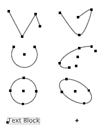 Figure 8.2: Shapes and Snap Point/Handles
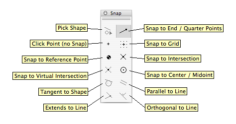 Figure 8.3: Snap Tools -toolbar
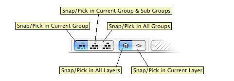 Figure 8.4: Snap Controls -toolbar
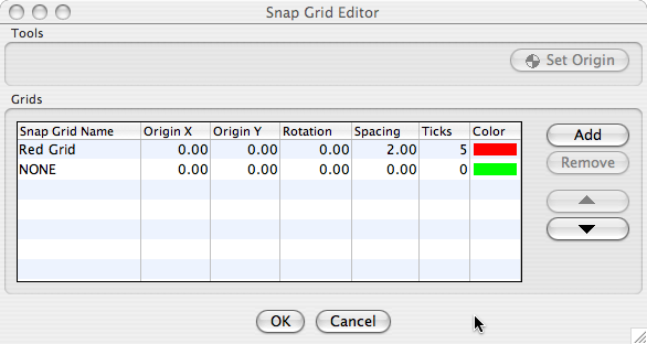 Figure 8.5: Grid Parameters -dialog
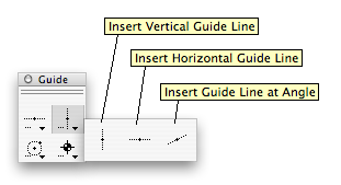 Figure 8.6: Line Guides -palette
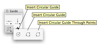 Figure 8.7: Circular Guides -palette
 Figure 8.8: Reference Point
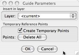 Figure 8.9: Circular Guides -palette
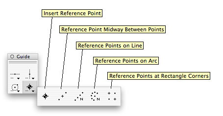 Figure 8.10: Reference Points -palette
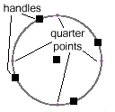 Figure 8.11: Circle Handles and Quarter Snap Points
 Figure 8.12: Coordinate System Origin -symbol
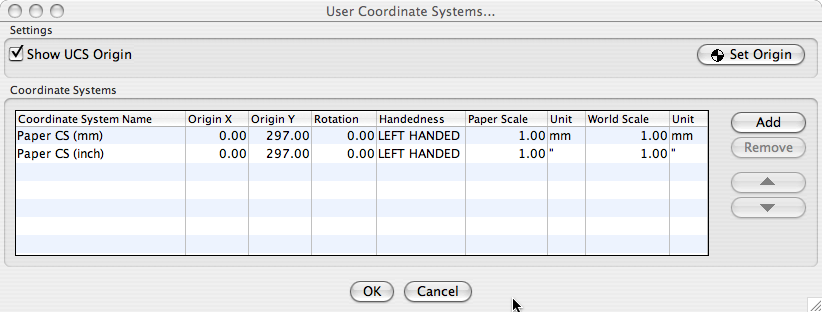 Figure 8.13: Coordinate Systems -dialog
 Figure 8.14: Last Point -symbol
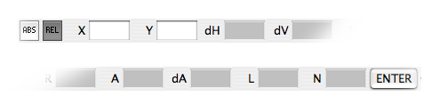 Figure 8.15: Numeric Entry -toolbar
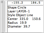 Figure 8.16: Info -toolbar
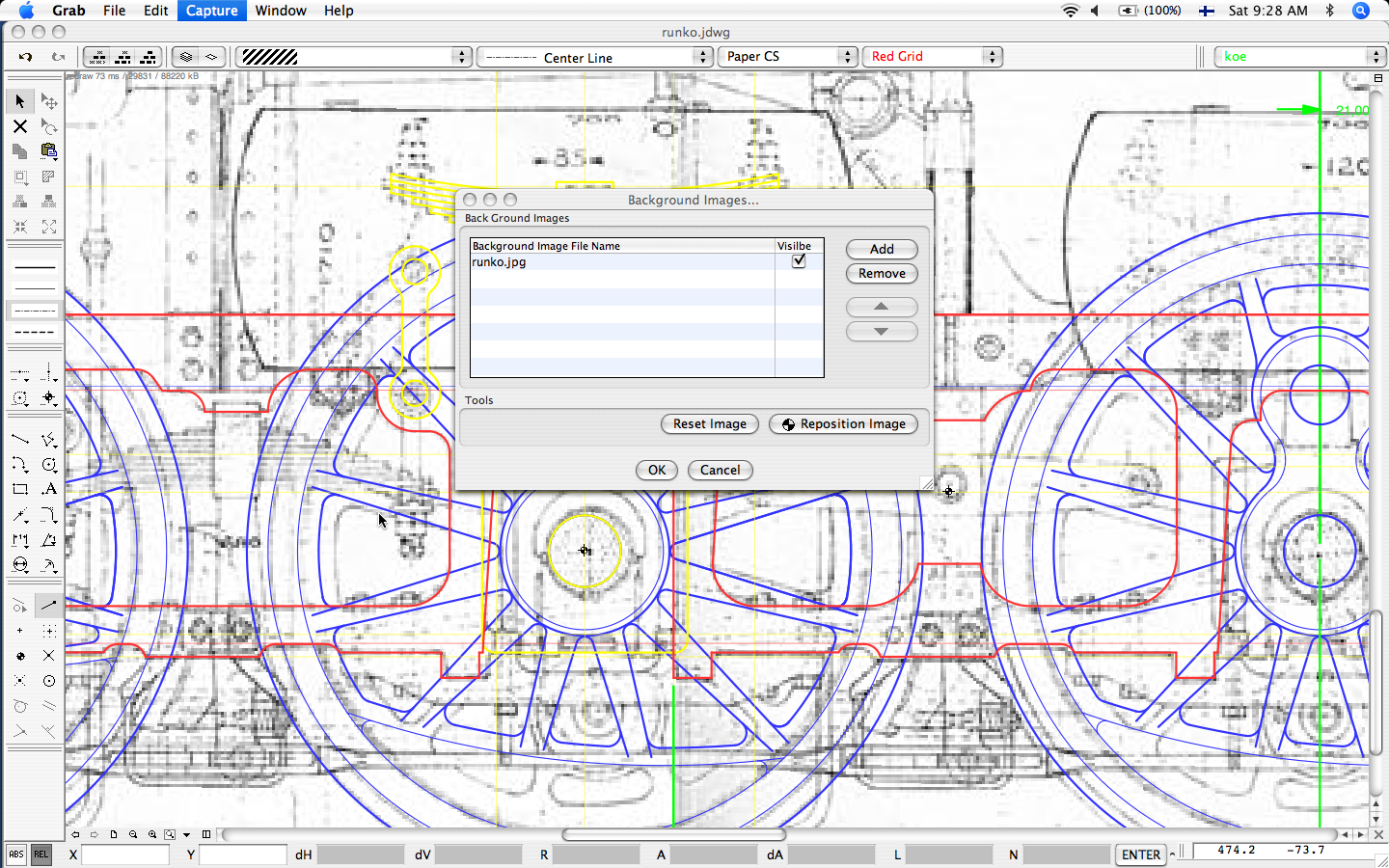 Figure 8.17: Example of Background Image Usage
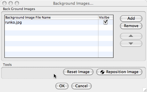 Figure 8.18: Background Images -dialog
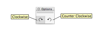 Figure 8.19: Arc Direction -options
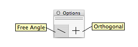 Figure 8.20: Line Constrains -options
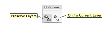 Figure 8.21: Paste Laeyr -option
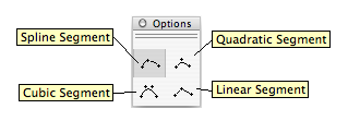 Figure 8.22: Spline Segment -option