|
|
A drawing consists of the following types of shapes or drawing primitives, see also figure 7.1:
|
|
In additions to these ’printable’ shapes there are also
which are visible on the screen but do not appear in the printout.
Except for Text Blocks and Filled Areas, for obvious reasons, each shape has a Line Style associated with it, which determines the width, color and dashing of the line that renders the shape.
Line Styles are shared between all shapes within a drawing so that changing/editing the line style affects the appearance of all shapes drawn with that Line Style. This is powerful and practical but is different from e.g. typical painting applications, where a line is drawn with one color and to change the color it is necessary to redraw with a different color.
Line Types are stored with the document and there is no explicit way to transfer line types from one drawing to another. However, if you copy/paste a shape from one document to another the Line Style is copied as well, of course. This does not create a link between the documents, so changing the Line Style in one does not change the other. Line Styles can be edited in the ’Settings/Line Styles...’ -dialog.
All shapes reside on a layer. Layers are the main tool for keeping your drawings manageable. As drawings get more complicated, especially with assembly or general arrangement drawings showing multiple overlapping parts, they soon become incomprehensible and impossible to manage without the use of layers.
There are a number of layering schemes, and you need to come up with one that works for you. Most people seem to use layers to differentiate between parts. This often makes sense as it allows you to turn off (hide) parts selectively. Different engineering disciblins have different needs.
A layer is like a transparent drawing sheet. The drawing document is made of a stack of such sheets. The layers have a back to front order which determines which shapes take precedence when shapes overlap.
The current Layer is displayed and can be changed with the Select Layer combo box on the top toolbar. The Layer combo box can also be dragged out of the toolbar and used as a floating toolbar, giving instant access up to 30 layers and their properties with a single click.
Layers have the following properties
No two layers can have the same name. Names are case sensitive. If a layer is not visible (is hidden) then none of the shapes that are on that layer are visible and cannot be picked, snapped to or in any way manipulated. It the layer is locked, the shapes on that layer cannot be manipulated or selected, but you can snap to them.
If the layer is snappable, you can snap to objects on that layer, otherwise they are ignored.
If the use color-attribute is set, shapes on that layer are displayed using the layer color, not the color dictated by the shape’s Line Style.
Shapes can also be grouped together. A group behaves like a single entity. If you select one of the shapes in the group, the whole group becomes selected. If you move one shape, the whole group moves and so on. Groups are not in any layer, but rather the shapes that make up a group are each in their own layer.
A group can also contain groups, so it is possible to have hierarchical structures that may help in managing drawing in certain situations. To form a group, you select the objects to you want to include in the group and click the Group button.
If the group contains reference points they become snap points and handle locations for the group, which is a very powerful way of creating ready to use parts that can be easily snapped into the right positions.
(If there are no reference points, an artificial reference point is calculated as the mathematical center of the bounding box in the paper coordinate system for all shapes in the group.)
It is possible to work inside or within a group, modifying the group without first ungrouping it. To do that, select a group and click the Work In Group button or simply double-click the group. When you are working inside a group all shapes that are not a part of the group are displayed as gray. When working within a group, all shapes you draw will be added to the group.
Text blocks are like mini word processing documents, in which you can use different fonts, sizes and styles (bold,italics). In order to be able to create precise layouts, the text blocks are layed out relative to a so called anchor point. The anchor point can be defined to be at key location relative to the text, for example in the beginning of the baseline of the first text line etc.
Filled Areas are created by selecting one or more shapes. The outlines of those shapes are combined together to form the boundary of the Filled Area, and the inside of that area is filled with the current Fill Pattern. The insides are determined using so called odd/even ruler, which works by drawing an imaginary line from a point to infinity and counting how many times the line crosses the boundary of the shape. An odd count indicates that the point is inside. Each Filled Area has four handles which also serve as snap points. These handles are at the corners of the bounding box of the boundary in the internal document coordinate system. As the bounding box is not precise, you do not want to snap to these handles.
Filled areas cannot be stretched.
Filled areas are always on a layer, but within in that layer they are behind all other drawing shapes except guide lines.
Fill Patterns are used to fill the area covered by selected shapes by pressing the Fill button.
Unlike Line Styles, the Fill Patterns are not shared between shapes and the Fill Patterns you see in the Select Pattern -combo box are not stored with the document, but in the file ’jDraft.patterns’. For the location of that file see Appendix A.
When a filled area is created the corresponding pattern is copied from the pattern file to the drawing.
Each fill pattern has a name and no two fill patterns can have the same name. Names are case sensitive.
The current fill pattern grid is displayed and can be changed with the Select Fill Pattern combo box on the top toolbar.
Fill Patterns come in three different types:
To edit the Fill Patterns bring up the Fill Patterns -dialogue, figure 7.2 with the Settings/Fill Patterns... -menu command.
|
|
Hatches are the traditional method of indicating cut away sections or surfaces on technical drawing. They are defined by:
You edit Hatch patterns by bringing up the Hath Pattern -dialogue, figure 7.3 selecting the pattern and clicking on the Edit -button on the Fill Patterns dialogue.
|
|
Typically, only the spacing and angle of the hatches are varied as the Line Style is dictated by drafting standards (usually a thin solid line). Sometimes, for example if an equally spaced hatch consisting of parallel lines needs to be created, it is necessary to use a different Origin for the two hatch styles, otherwise the lines will simply overlay each other.
If cross-hatching or hatching with alternating line styles is needed it is necessary to hatch multiple times with different patterns.
Figure 7.4 shows some typical hatch pattern combinations used in engineering.
|
|
When multiple filled areas with the same fill pattern overlap, the patterns ’blend’ together, which is desirable as, if e.g. the hatching of an area needs to be done in parts it is important the hatches appear continuous.
You edit Solid patterns by bringing up the Hath Pattern -dialogue, figure 7.5 selecting the pattern and clicking on the Edit -button in the Fill Patterns dialogue.
|
|
Solid fills are simply areas filled with a single, solid RGB color.
Raster Patterns are based on tiling a picture side by side to cover the Filled Area.
You edit Solid patterns by bringing up the Hath Pattern -dialogue, figure 7.6 electing the pattern and clicking on the Edit -button in the Fill Patterns dialogue.
|
|
Raster Patterns are created from image files (TIFF,GIF,JPEG and PNG formats are supported).
Raster Patterns are very powerful and can be used to created any kind of fill effects. However, the resulting output quality is defined by the resolution of the image used to create the pattern.
There is a tradeof between the accuracy (resolution) and file size. Obviously to create the perfect, for example ’concrete’, pattern one would draw by hand a A4 sized sample, scan it at 300 DPI resolution and import it into fill pattern. Unfortunately, this would create a pattern of size 210x297x(300/25.4)2x4 bytes, a whopping 34 MBytes!
So the recommendation is to use patterns about 100 x 100 pixels at 72 DPI or thereabouts. This creates patterns of about 40kB in size and produces an acceptable output on a typical office printer.
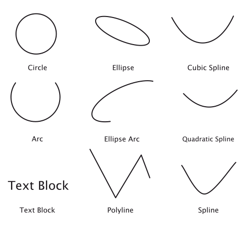 Figure 7.1: Drawing Primitives
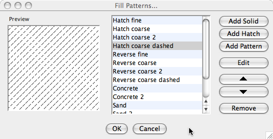 Figure 7.2: Fill Patterns -dialog
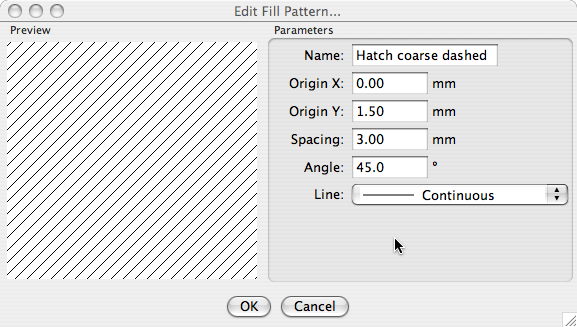 Figure 7.3: Hatch Pattern Edit -dialog
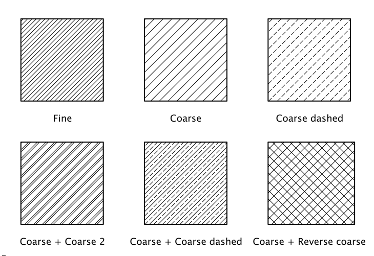 Figure 7.4: Hatching Combinations
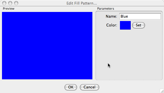 Figure 7.5: Solid Pattern Edit -dialog
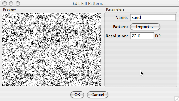 Figure 7.6: Raster Pattern Edit -dialog