|
|
You find this command from the right click menu, figure 5.5.
Sometimes you need to do some drawing operation that jDraft does not support. In general, the support for all drawing operations is orthogonal so that everything works with/on anything. A notable exception is spline curves. Figure 11.4 shows an example of exploding a Spline.
Although you can snap to the intersection of splines you cannot cut or split the line at that intersection. Instead you need to turn the spline into a polyline with the Explode command from the right click menu.
All items, except Text Blocks and Filled Areas can be ’exploded’.
Note that there is no ’un-explode’ command so you cannot turn a polyline into a spline. You can, though, ’Join’ line segments to create a single polyline.
|
|
You find this command from the right click menu, figure 5.5.
This command moves all selected shapes to the current layer.
You can add / remove points to/from polylines and splines with the Add Vertex / Remove Vertex tools. Just point and click on the polyline to add/remove vertexes. Figure 11.2 shows the spline tools palette.
|
|
Very often in techical drawings, which is not simply a drawing process but a design process as well, the need to trim away excess length of a line or split a line at the intersection of another line, arises. Figure 11.4 shows an example of trimming. To trim a line, select the Trim tool, first point at the line segment to be removed and then the intersecting shape. The line segment to be removed will be indicated by X-marks at the ends.
|
|
Splitting is analogous to trimming - if the excess is not removed, the shape is simply split at the intersection. Lines, arcs and circles can be trimmed/split. Polylines can also be split at a vertex with the Split Polyline at Vertex-tool, which is preferable to the split tool, which would in a situation like that generate a very short line segment.
|
|
Typical turned or machined parts exhibit chamfering of edges as illustrated in figure ??.
|
|
These are added at the end of design phase, i.e. the part is first drawn without these features and the chamfering added.
|
|
Figure 11.7 shows the Filleting Parameters -dialogue, which contains also the chambering parameters. To chamfer, set the chamfer size and method in the chamfer dialogue and then pick two line at a corner to chamfer. Chamfering adds a line and trims the two lines. It is also possible to setup the tool to not trim the line, which can be handy at times.
|
|
Filleting is analogous to filleting, except that a semi circle / arc is used to ’round up’ the corner.
The Resize / Mirror -palette provides commands to resize and mirror selected shapes. The Resize command always transforms the selected shapes, whereas the Mirror commands create transformed copies.
To Resize shapes, first select the shapes to be resized, then click on the Resize tool, pick a line and numerically enter a new length for that line.
To Mirror shapes, first select the shapes to be mirrored, then click either the Point Mirror or Line Mirror tool and then enter a point or pick a line to mirror against.
|
|
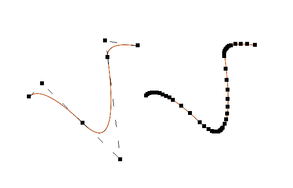 Figure 11.1: Exploding a Spline
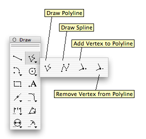 Figure 11.2: The Spline and Polyline -tools
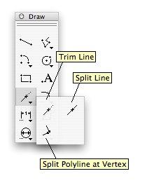 Figure 11.3: Trim and Split -palette
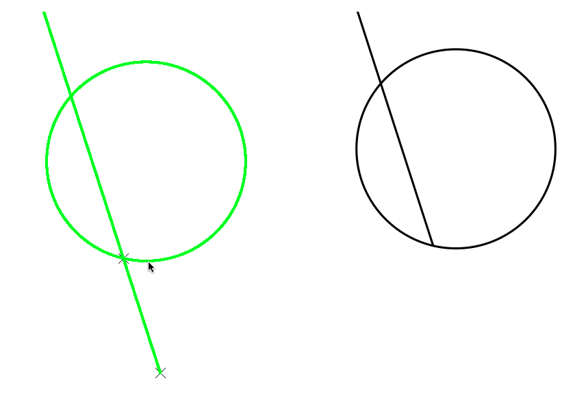 Figure 11.4: Trimming a Line
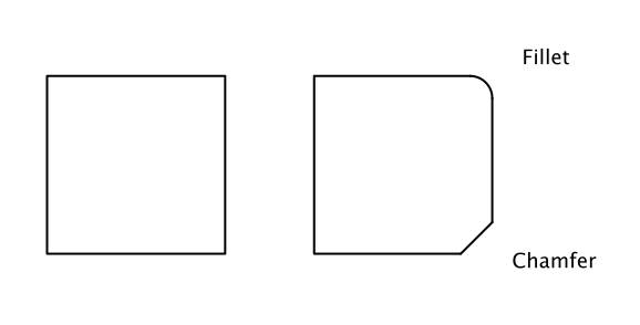 Figure 11.5: Fillets and Chamfers
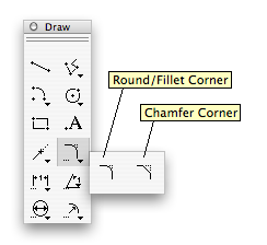 Figure 11.6: Fillet and Chamfer -palette
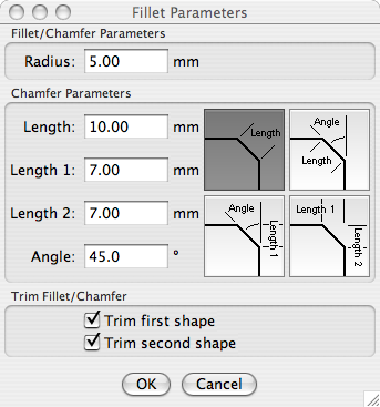 Figure 11.7: Fillet Parameters -dialog
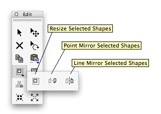 Figure 11.8: Resize / Mirror -palette