|
|
Before you draw you probably want to set the coordinate system, or at the very least set the scale, so that you can enter and see dimensions in the real world units. Go to the Settings/Coordinate Systems... , add a new coordinate system (it is a good idea not to modify the standard Paper Coordinate system) and set the ’world’ and ’paper’ slices and units.
You can also set the current coordinate system using the top toolbar, figure 10.1 and setup the coordinate systems in the Settings/Coordinate Systems... dialogue.
|
|
Any non-trivial engineering drawing uses layers to distinguish things like constructional aids, sketchings, dimensioning etc. by color. As you will be changing the layer frequently as you draw anyway, tear down the Layer toolbar, figure 10.2 and set up the layers and colors as necessary.
|
|
You can also change the current layer with the top toolbar, figure 10.1 and change the layers in the Settings/Layers... dialogue, figure 10.3.
|
|
Most users seem to rely on a grid even if the actual drawing is done with geometric construction and dimensions, the grid seems to provide a sense of scale and comfort. You set up the grids Settings/Grids... dialogue and you select the grid in effect from the main toolbar, see figure 10.1.
Select the line style for drawing from the top toolbar, figure 10.4, if there is a selection when you change current line style, the shapes will be changed to use that line style.
|
|
For quick access to four Line Styles, the line style can also be selected from the quick buttons on the ’Lines’ toolbar on the left, figure 10.5 To configure these buttons, right-click the button or hold the mouse button down until the menu appears.
|
|
To edit the Line Styles, bring up the line style editor dialogue with the Settings/Line Styles... -menu command.
|
|
On last count there were over 150 drawing rules or commands, not counting their options, so obviously it would be as futile to list them as it would be to try to learn them. Fortunately, this is not necessary.
|
|
Basically it is very simple, select the shape you want to draw and then point and click with the Snap tools. To draw a line, click on the Line tool and then click two points on the drawing area to create the line.
The real power of the user interface comes from the way it deducts what you are drawing.
Need to draw a circle with a given radius? Click the circle tool, then click on the radius entry field, type in the radius, and click the drawing to specify the center.
Need to give then center with numbers, just click and enter it in the X and Y entry fields.
Want to draw a tangent to a circle? Select the Line tool, then select the Tangent snap, click on two circles or click on a point and a circle.
The best way to get the hang of it is to try.
|
|
|
|
Splines come in three variations, see figure 10.10. The main difference between the splines is how they pass through/near the control points. Catmull-Rom, called simply Spline, always passes through the control points, Quadratic splines pass through every other control point and Cubic splines pass through only every third control point.
|
|
To create a spline, select the Spline -tool and enter the control points. With the Options -toolbar, figure 10.12, you can select the type of spline you create. Different types of spline segments can be used in a single spline. Note that unless the number of control points ’match’ the segment type (i.e. quadratics need two points for each segment and cubic need three), the results do not look pretty.
To end a spline click on the spline toolbar button again, or press ESC key. You can also use the End Spline or Close Spline commands from the right-click menu, figure 10.13
|
|
|
|
|
|
It is amazing how often drawing follows a pattern; you draw a line, snap to the line end point, snap to the circle center ad lib. You draw something else and when you come back to circle drawing, the same patterns repeats. The jDraft user interface takes advantage of this with a feature called Auto Snap. When you select a drawing tool and when you select a Snap tool, the software makes a note of that and the next time you do the Draw tool selection under similar circumstances the software clicks the Snap tool for you! If this default is wrong for your situation, just click the correct snap and the software learns that.
In the old days, before the modern mouse based user interfaces, the norm in CAD was to click twice to draw a line. Then came Apple Lisa and the public learned to point, press, drag and release to draw a line. Both systems have their advantages and disadvantages. Fortunately, jDraft users do not need to choose. You can use either way - the software automatically adjust to your gestures.
setup coordinates, scale, maybe grid, layers, select layer and select line style
When you select the text drawing tool and enter a point, a new text block is created and anchored on that point. A small Text Editor appears where you can edit the text, see figure 10.14. To close this dialogue, you either click on the Close symbol on the dialogue title bar, or press ENTER -key.
In engineering drawing most text is just one line of text, so the use of ENTER key to dismiss the dialogue is handy. If you need to enter multiple lines in the same text block, use SHIFT-ENTER to get to the next line. If you find yourself doing multiple text line entries all the time, you can turn off the close-with-ENTER feature.
|
|
There are two ways to enter text, either before or after you place the text block. This can be set in the Preferences -dialogue. In the text-before-placement mode, whenever you click the Text -tool the application prompts you for text and then you can place one or more copies of that text with the mouse. In the placement-before-text mode you first select the text tool, then click to indicate the text location and the application prompts for the text.
The text is layed out relative to the anchor point, which you can set to be on the left/top, center or bottom/right in the horizontal/vertical direction. In the vertical direction, the aligment can also be on the ascender,descender or baseline of the first or last text line. For these lines, refer to figure 10.15. This makes easy to control precisely how the text block is positioned and how it will grow.
|
|
Shapes can be grouped so that they behave like a single entity. To do that, select the shapes and either click the Group Selected Shapes button or select it from the right click menu. To ungroup, use the Ungroup button/menu item. It is possible to work inside or within a group, modifying the group without first ungrouping it. To do that, select a group and click the Work In Group button or simply double-click the group.
When you are working inside a group, all shapes that are not part of the group are displayed as gray. When working within group all shapes you draw will be added to the group.
To exit the group, select Exit Group from the right click menu or double-click on ’nothing’.
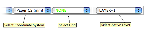 Figure 10.1: Coordinate System, Grid and Layer -controls
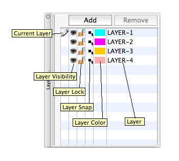 Figure 10.2: Layers -toolbar
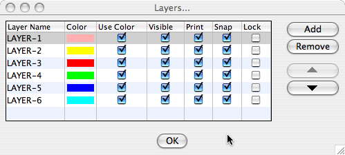 Figure 10.3: Layers -dialog
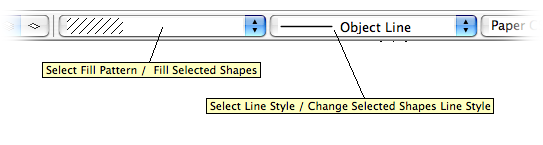 Figure 10.4: Fill and Line -controls
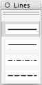 Figure 10.5: Lines -toolbar
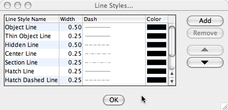 Figure 10.6: Line Styles -dialog
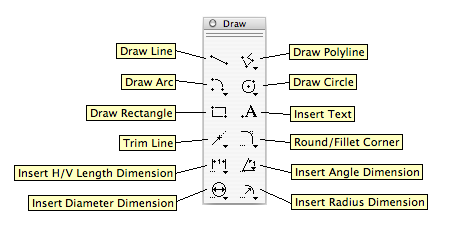 Figure 10.7: Draw -toolbar
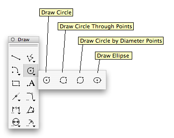 Figure 10.8: Circles -palette
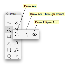 Figure 10.9: Arcs -palette
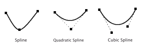 Figure 10.10: Catmull-Rom, Quadratic and Cubic Splines
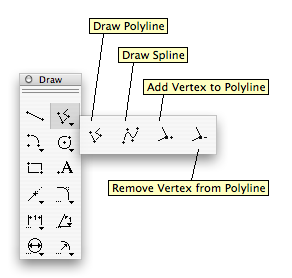 Figure 10.11: Polyline/Spline -palette
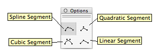 Figure 10.12: Spline Options -toolbar
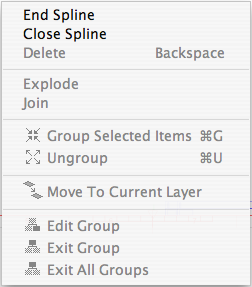 Figure 10.13: Spline Right Click -menu
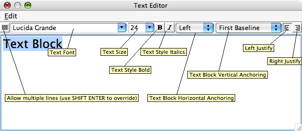 Figure 10.14: Text Editor -dialog
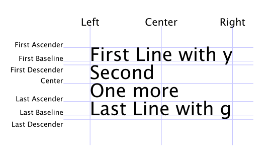 Figure 10.15: Text Block Alignment