I HAVE RECEIVED INFORMATION THAT THIS COPYRIGHTED WEBPAGE HAS BEEN STOLEN, COPIED AND SOLD ON E-BAY AS A "BOLEX MANUAL". IF YOU INTEND TO BUY A "BOLEX MANUAL" VIA THE INTERNET, PLEASE ASCERTAIN THAT YOU ARE BUYING ORIGINAL MATERIAL, NOT SOMETHING PIRATED AND SOLD FOR PROFIT BY UNSCRUPULOUS PERSONS. IF YOU HAVE SEEN THE MATERAIL BELOW FOR SALE, OR BOUGHT A MANUAL CONTAINING IT, BE WARNED THAT IT IS WITHOUT THE AUTHOR'S PERMISSION. PLEASE INFORM THE AUTHOR OF ANY SUCH COPYRIGHT BREACH, THANK YOU!
SUPER-16 modification of Bolex Reflex 16mm camera
Please note: This page contains many images (total: 210K). If you want to see them all, you'll have to wait a while...
It is possible to make a S-16 modification of a Bolex
spring-wound reflex camera - but you need some dexterity, familiarity
with tools, and a fearless mind to attempt this yourself. WARNING: Be careful! I take no responsibility
if you damage your camera (or yourself!) when you follow these instructions!
For this reason, I won't give exact instructions on how to perform this work, rather I give a description of how I did it myself...
If you feel you are not familiar enough with the innards of a Bolex, and don't have a ready source of spare parts (in case you botch something), DON'T DO THIS!
This S-16 modification can be made just with hand tools, but using a lathe and mill will get a much better looking result! I have indicated the differences when using a lathe/mill in the "NEW INFO" boxes.
| NOTE: Since there are many different models of Bolexes, you should, before you start any modification, check all the details of your camera and compare them to this description. If there are differences, you may have to modify the procedure or some details of it. This page applies only to Rex3, Rex4 and some earlier Rex5 models. The newer Rex5 & SBM models have different viewfinder optics, with a thick condenser lens instead of two thin ones. This requires different modifications. Also, the Bolex EL model includes a delicate light meter mechanism, so I strongly recommend you NEVER open up a Bolex EL! |
Of these, only step 1 is absolutely necessary. If your lenses have a
wide enough coverage (most fixed focal length Switars have, except the
very shortest focal lengths), you can manage without step 2, and if you
don't mind having to estimate the new image area when framing your
shots, you can do without the finder modification.
Phase 1: Enlarging the gate to S-16
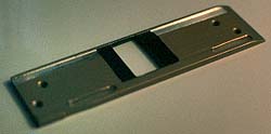
First, I disassembled the front of the camera:
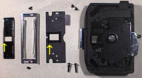
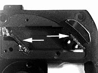
Here you see, from left to right, the gate, the edge guide, a light baffle plate and the rest of the camera front. The arrows indicate which parts need to be modified, and where.
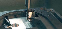
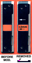
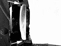
First, the gate. Originally, the aperture is 10.26 mm wide, and it should be enlarged to 12.35mm, i.e. an enlargement a hair's width over 2 mm. I did this using an ordinary small metal file. I filed the aperture to almost the right size just by eye, and then started to use a micrometer to check the progress - so I could stop when the size was right...
I also had to file away some of the non-perf-edge "rail", that otherwise would have touched the film in the image area, and might have caused scratches. If you look closely at the above image, you can see what I had to do.
 NEW INFO: NEW INFO:There are two types of gate, made of either anodized aluminum (yellowish, see finished work, left) or hardened steel, above. The aluminum gate is easy to modify (but be careful not to scratch or crack the anodization where it will touch the film), using a milling tool on a lathe or miller. The steel gate cannot be milled with ordinary tools, it's too hard - it has to be ground, or milled with carbide tools, or, as I did on my first try, filed by hand - hard work! Standard SMPTE 201 specifies the Super-16 "Type W Camera Aperture Image" area as 12.35 x 7.42 millimeters. (The area extracted for 1.66:1 is 11.80 x 7.10 mm, and the area extracted for 1.85:1 is 11.80 x 6.38 mm.) The vertical centerline of the image is 9.00 mm from the reference edge (perforated side) of the film. |
I also opened the aperture in the light baffle plate, by 2 mm. After blackening the metal where the filing had caused a bright surface both on the plate and the gate, I re-assembled the front, and attached it back on the camera. When this is done, care must be taken that the shutter gears are positioned correctly. This is a trial and error process. If incorrectly assembled, the camera will expose the film while it is moving, causing blurred images. There is a simple way to check if the assembly is made correctly: Set the camera's I/T knob to T, press the side release forward, and hold it there. Check that the shutter blade's upper edge is just about coming to the top of the gate - if not, remove the front, turn the shutter a little, re-assemble, test again. When you finally get it right, secure the front with its screws.
Also note that the front must be light-sealed after a disassembly: Using black paint, fill the cracks inside the camera, around the front assembly. (The original paint cracked when the front was removed.) If this is forgotten, light leaks may occur in strong light.
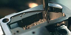
It almost goes without saying that the sound-track side flanges of the sprockets must be reduced or removed.
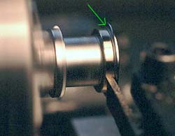
 The best way to remove the flange is on a lathe, even though hand tools can be used.
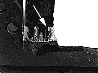
It is a good idea to make what is left of the flange a
little conical. However, DO NOT remove the innermost little protrusion
of the flange (about 1/2 mm wide, marked in green in diagram, and with
arrow in photo), because it will actually support the edge of the film.
Phase 2: Centering the lens holder
This was rather easy: using a round file, I enlarged
the center hole of the rotating plate so that the front could be
displaced 1 mm (towards the film loading side) of the camera:
When reassembling the front, I inserted into the enlarged hole, opposite the enlargement, a spacer of brass that pushed the plate to its new location. Using the original Bolex securing lens cap and the small securing plate on the top of the camera front, the plate is held firmly enough for small lenses. It may not be enough for very heavy zoom lenses, though. Also note that the lens holder cannot be rotated when centered for S-16. To rotate, it must be re-assembled for regular 16 (i.e. the spacer put on the other side of the center pivot)...
 NEW INFO: NEW INFO:There is a better, but more tedious way of centering the lens for S-16, but you need a lathe/mill and quite some dexterity to do it:
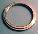
A new C-mount thread is made and installed in the front revolving plate
of the camera. This threaded ring must be turned to exact dimensions,
with suitable flanges for mounting.
|
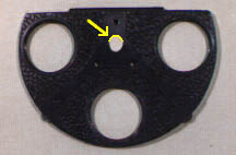
Maurice van Bavel from Belgium has a quick and easy solution for re-centering the front:
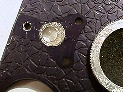 "As you can see in the picture, I drilled the center hole of the
rotating plate with a drill 2 mm larger than the original hole. I moved
the plate 1 mm to the right and filled it up with epoxy, after putting oil on the camera axis. So the plate can still rotate for cleaning the reflex prism."
"As you can see in the picture, I drilled the center hole of the
rotating plate with a drill 2 mm larger than the original hole. I moved
the plate 1 mm to the right and filled it up with epoxy, after putting oil on the camera axis. So the plate can still rotate for cleaning the reflex prism."
|
Thanks, Maurice! I've done a similar mod myself, by machining a brass bushing to fit in the enlaged hole. The bushing has an off-center hole that moves the front the required 1mm. I also made a spare bushing with a centered hole, so I can reset the front to the normal 16 position just by exchanging the bushings.
Phase 3 - the finder modification
Here is a view of the finder system of the Bolex reflex cameras:
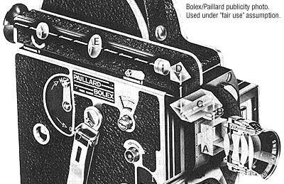
Starting from lower left, behind the lens, is the beam-splitting/focusing prism A, which directs approx. 25% of the incoming light to the finder, the rest to the film. This prism contains a transparent diagonal mirror that reflects the image up through the condenser lenses B to the periscope prism C, which reflects the light path twice. Still another prism, D, finally turns the light through the finder optics E towards the cameraman's eye.
This system has to be modified to enable the entire S-16 image to be visible in the viewfinder. It is also necessary to add a finder reticle to the focusing prism that enables the cameraman to see the exact S-16mm framing - I have published instructions on how to make the finder reticle elsewhere on these pages. I recommend the use of the dual 16/S-16 reticle. The estimate is then easy: Two more columns will show on the right side in the S-16 image, than in regular 16mm. Follow the instructions given on the page to properly make and install the reticle.
Please note that a finder reticle MUST be installed BEFORE the following actual finder modification is performed - otherwise there is no easy way of correctly making the original reticle (Unless you have a second camera, of course!) See the aforementioned reticle instructions!
To attempt the finder mod, the front of the camera must be disassembled almost completely: The shutter must be removed, as well as the focusing prism assembly, the condenser lenses, and the finder periscope prism. IMPORTANT: Do NOT touch the laquered prism A adjusting screws, just the 2 screws that attach the whole assembly to the front - if you accidentally turn the adjusting screws, the finder will be out of focus and will probably need professional work & collimating equipment to get back to normal!
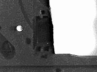
After dissassembly, I could start modifying the metal... Here you see the original front with ground glass condensers removed (they were held by the grooves you see here).
Next, with a small file, I removed almost all of the grooves on the "film loading" side of the front. I left only a very small "step" of the groove nearest the focusing prism (see arrow):
Then, I replaced only one of the condenser lenses, the one closer to the focusing prism, and secured it with a minute amount of glue, at arrows:
Next, I had to modify the periscope: Since the S-16 image is 20% wider than the regular image, it wouldn't "fit" through the original finder optics. I removed the prism, and attached two thin front-surface mirrors (with hot glue!), at arrows below.
This is painstaking work - I had to estimate the position and 45 degree angle of the mirrors as exactly as possible: I reattached the focusing prism, and peered through the whole assembly to check that the ground glass image was level and centered on the optical path when adjusting the exact position of the mirrors. This was a trial and error process - luckily, hot glue can be adjusted for a few seconds after application, and it is rather easy to peel off if the mirror position is wrong.
Now, I could reassemble the front. This left one more thing to do: Since the optical path got longer when I substituted the periscope prism with the front-surface mirrors, I had to add an additional negative lens element in the finder tube (at A):
This new lens refocuses the image to the correct plane, and it is around -2 to -3 dioptries (i.e. a 330 to 500mm negative focal length. I can't tell exactly, because I have half a zillion unmeasured miscellaneous lenses in my drawer, and I just picked a suitable one...). The exact placement of the lens must be found by trial and error. I attached it with, handy stuff again, hot glue (at A)! Care must be taken so that the new lens does not obstruct the finder closing flap (D).
The finder's original mask (B) is now of incorrect size. It must be removed. Since there is already a finder reticle installed, the mask is not necessary for framing anymore.
Then, the last step is to adjust the prism in the finder tube so that the image is centered in the finder. This is done with the three adjusting screws (C).
|
After doing these modifications, I tested the camera thoroughly, before I shot anything important...
WHEW! Some job, eh? If you ever do this yourself, please e-mail and tell me about it...
|
LluĚs Casasayas writes:
I have done it in 2 differents Bolex (rex2 and rex5) with full successful!! This is what I made:
This way has the advantage that the torret remains fully operative (all 3 lens centered) and the shutter and the viewfinder system are also "natural centered" with the new super 16 gate (don't need condenser lens-prism modifications).
Thanks, Lluis, for that info! |
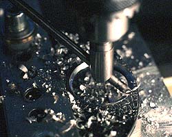 This
procedure also necessitates routing a hole where the old C-mount thread
was. The operation must be done with high precision, in the exactly
right position and with the right dimensions to let the above ring fit
in. Here I use a home-made, adjustable "fly cutter" to route the hole
to the same diameter as the threaded ring. Naturally, this hole must
also have a flange, against which the ring will be seated.
This
procedure also necessitates routing a hole where the old C-mount thread
was. The operation must be done with high precision, in the exactly
right position and with the right dimensions to let the above ring fit
in. Here I use a home-made, adjustable "fly cutter" to route the hole
to the same diameter as the threaded ring. Naturally, this hole must
also have a flange, against which the ring will be seated.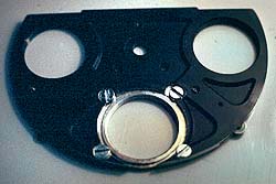 Then,
the ring is mounted in the routed hole with countersink screws. No
protrusions are allowable on the back side, since the plate has to
revolve freely.
Then,
the ring is mounted in the routed hole with countersink screws. No
protrusions are allowable on the back side, since the plate has to
revolve freely.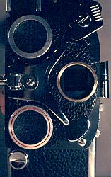 This
is how the final result looks like. The middle lens C-mount is now
centered for Super-16 use, the two others are still at standard-16
center. The two upper mounts can be modified, but he lower one must NOT
be - it has to take the special locking cap (with red ring), that keeps
the front plate in position when using heavy lenses.
This
is how the final result looks like. The middle lens C-mount is now
centered for Super-16 use, the two others are still at standard-16
center. The two upper mounts can be modified, but he lower one must NOT
be - it has to take the special locking cap (with red ring), that keeps
the front plate in position when using heavy lenses.