jDraft Tutorial
This is a tutorial for jDraft - a simple drafting program with CAD-like features.
Copyright 2004 - Kustaa Nyholm
| Hope you find this tutorial usefull, |
| regs Kusti / Siuntio 14.3.2004 |
P.S.
Special thanks to my wonderful daughther Sandra for creating the numerous screen shots and for proof reading the text.
Version History
Version 1.0 of this tutorial 14.3.2004
Version 1.1 of this tutorial 4.4.2004 (Small updates, but still not fully up-to-date with version 1.0.0.4b)
Note that version 1.0.0.6b of jDraft introduced some major changes and improvements to jDraft ,
so please read the release notes
along with this tutorial.
Preface
Writing good manuals is difficult, so I won't even try. And while I've been known to read through
a thousand pages over a weekend to get to know something, in general I'm not good at learning by
reading, instead I prefer exploring and doing.
Unlike most manuals, this is not a walk through of menus and features. Instead
I try to explain the principles and concepts involved. I hope this will get you started. I have
no plans to keep this tutorial up-to-date as the software evolves. (Incidentaly, I changed the button look just
two days after completing this tutorial, thus the images are out of date. If you want to see buttons like in this
tutorial, go to the 'Tools/Tune Up...' menu and uncheck the 'Toolbar Buttons' checkbox.)
like toolbar buttons (i.e. without outline, except when mouse is over the buttonInstead you should look at the
revision history for new features, or better yet, explore the software. I have indeed failed in
creating the software if you cannot use it armed with basic introductory text and the software itself.
I think the program is pretty easy to use, so you might just start using it and skip this tutorial (not
recommend) but you still might like to see the 'Common Problems' section at the end of this page.
Introduction
jDraft is a simple 2D drawing program for creating engineering drawings. It has an interesting history
which I hope to write down someday. On the superficial level it resembles simple drawing programgs
such as my old flame MacDraw or later day OpenOffice-Draw. But there is a marked difference. Anyone
who tries to draw accurate drawings (that would conform to good draftmanship guidelines) with these
programs soon finds out that it simply is not possible. The main design goal of jDraft was to make
it possible to
draw geometrically accurate/correct drawings in a simple and natural way, not unlike the time honored
way of using a compass/divider and a straight edge. With out bad mouthing any particular software I
think it is fair to say that while those programs allow the creation of accurate drawings many of them
are not that easy to use. I hope that jDraft proves to be an animal of different color.
Basic Concepts
a Drawing is a Document is a File
The main concept of a drawing is , well uh, a drawing. A drawing has a size (width and height)
that corresponds to the actual paper size when the document is printed out. In the computer hard disk a drawing
is stored as a file (with extension '.dft') and on the screen it is represented by a window that displays
the drawing and the tools needed to draw/edit the drawing and tools for view control.
All program setting (with a few obvious exceptions) are stored in the document file and thus changing these
in one document does not propagate those changes into any other drawings.
Layers
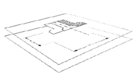 |
| Visualising layers |
A drawing is made of layers. A layer can be visualized as a transparent sheet (how do you visualize
transparency ;-) on which the lines and shapes that make up the drawing are placed. Layers can be hidden or shown
at will facilitating organization of information in the drawing.
You can for example draw actual parts
onto one layer and do the dimensioning in the second and thus it is possible to hide the dimension
while working on the parts. Layers have a back to front order that
determines overlap order, you can control this back to front order.
Each layer has a name which can be set by the user. Each layer can be
independently hidden/visible and printable/non-printable. Each layer has a user setable color associated with it,
this can be set to override the actual object colors on a layer by layer basis.
Grids
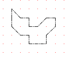 |
| A sample grid |
Like most CAD programs jDraft support grids, which are a orthogonal mesh of snap points that make it easy
to draw accurately regular features. (In case you did not know, snapping usually refers to a feature
in which you only need to point close to what you want and the cursor (or what ever) will snap tot the
correct location.) A grid has a name and a color that can be set to be able to distinquish them.
Each grid has of course a spacing and tick mark value associated with it that defines the snap spacing and visible tick
mark spacing. In addition to that each grid has an origin and rotation, so that the grid can be aligned
with any point/feature in the drawing, such as a floor plan base ref point and wing of a building at angle.
Any number of grids can be defined.
Units / Coordinate Systems
 |
| UCS origin icon |
All numeric measures input to the software or displayed by the software are always in a user selectable unit and scale.
The default unit is 'mm' (milli meters) but imperial (decimal not fractional) units are also available. The scale in use is
defined by the selected User Coordinate System (UCS). Any number of coordinate systems can be defined.
A coordinate system defines the relationship between the drawing and the real world that the drawing
represents. The coordinate system is defined by origin (the point that has coordinate values 0,0), a scale (the
ratio of measures on paper versus in real world) and a rotation angle (defines which way real world 0 deg angle points
to in the drawing). In addition to that the coordinate system can be left handed (as we learned in the school) or
right handed (preferred by software people). Any number of coordinate systems can be defined and one of them is
always selected (active/current). The selected coordinate system is used when ever values need to be displayed or
entered, for example in dimensioning or numeric entry.
The coordinate system defines (i.e. the rotation angle and handedness define) what is horizontal and vertical for the software.
This is worth noting as when you draw a rectangle, the sides of the rectangle are aligned with the coordinate system
X/Y axises which may not be aligned with either the screen or paper horizontal/vertical axises.
Line Styles
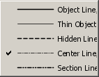 |
| Example line styles |
All (well most) shapes are drawn in a specific line style. A line style defines the width, color and stroke (dash)
pattern of the line. The line styles are named and you can define any number of line styles you want. You can change
the name, stroke (dash) pattern, color and width of a line style. (But at present you cannot create new stroke patterns,
you have to be contend with what the software has to offer.)
Changing a line style affects all shapes (already) drawn with that line style. The idea is much like the styles in
a word processor. You should draw lines with specific style, not with specif width or dash pattern or color. You
can change these at any time later. So if two line represent the same kind of thing, like the outline of a part,
use one style, but if they represent something different use different line styles, even if they would look the same.
When pasting and/or importing shapes, the question of what line style to use comes up. At present this is based on names,
in other words, if you copy something from one drawing to an other, the styles (based on names) are retained, which means
that a shape that appears thin and dashed may appear thick and solid in an other drawing if the line style definitions
are different.
A good practice in this respect and in many other ways too, is to create
an 'empty template drawing with your preferred settings and start each drawing from that template by 'Save As':ing it with
a new name (do take care to start by saving in order not to trash you template).
Hatch Styles
 |
| Sample hatch styles |
A hatch style defines how a hatch area is filled. At present only the line style, angle and spacing of the hatching can
be changed. I hope to offer more advanced fill patterns in the future. You can define any number of hatch styles.
Drawing Objects aka Shapes
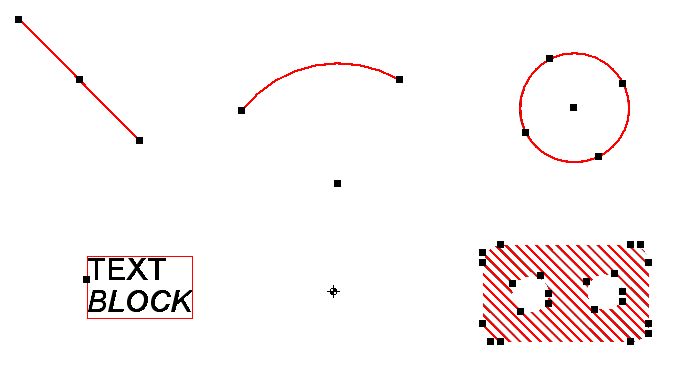 |
| jDraft shapes |
At the time of writing this tutorial, jDraft supports six types of objects, ie shapes you can draw.
These are lines, arcs, circles, hatched areas, text blocks and reference points. (I have plans to add support for
elliptical arc, ellipses, true polylines and spline curves in the future.) Each shape has one or more handles (those
small black boxes) that can be used to stretch the shapes and to which you can snap into.
Lines, arcs and circles are
pretty selfexplanatory line elements, drawn with a specific line style. Lines and circles can also be drawn as guide lines.
Guide lines are shapes that have a specific line style (that you can edit) and that are not printable. Otherwise they behave
like any other shapes.
Text blocks are rectangular areas of text, arranged as multiple lines of styled text. Currently different fonts and
sizes as well as bold and italic fonts are supported.
 |
| a Referece Point |
Reference points are non printing points that you can snap to and which always
look the same on screen, regardless of how the drawing is zoomed. Reference points come in two varieties, permanent
and temporary. A temporary reference point disappears as soon as you create a shape that has a snap point that
coincides with a temporary reference point. The rationale is that a) you do not want to fill your drawing with
reference points and b) as soon as there is a shape with a snap point at a particular location the ref point at that
location becomes superluous.
Main User Interface Parts
The following screen shot identifies the main user interface parts.
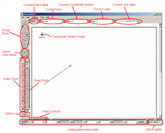 |
| User interface main parts |
Of Buttons, Dialogs and Popup Menus
Mac or CAD
Most Win/Mac softwares draw lines by requiring the user to press-drag-release with the mouse to create a line, whereas
a lot of CAD programs are based on the click-click principle. Which is better is a matter of opinion, although
the latter (CAD style) has the undeniable advantage that you can click something else (like change the snap options)
while drawing a line, something that is not feasible with the press-drag-release style. Anyway, in most cases both
styles can be used with jDraft, you can press-drag-release or click-click in most situations.
Note that to 'box select' and 'box zoom' you need to use Mac i.e. press-drag-release style.
Panes
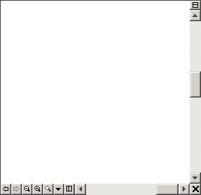 |
| a Pane with View Controls |
The main part of each drawing window is taken up by a drawing area, called pane. This pane displays a zoomed
in/out part of the drawing. So the pane is really a 'window' to the drawing through which the drawing is viewed
and drawn, edited. A pane can represent a rotated view of the drawing,
e.g. in architectural plans, where many buildings have wings that are at an angle, it is easier to design and draw
if the features are aligned with the screen even when on paper they are at angle.
Multiple Panes
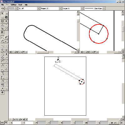 |
| Multiple Panes |
You can have multiple panes into a single drawing making it possible to have both overview of
the whole drawing and zooming in at a detail at the same time. Or zoom in at two small details far apart and draw
easily and accurately e.g. line from one pane to other. To create multiple planes you split a pane in two by clicking
at the split icon. To create a pane arrangement like
on the left, you first split the main pane vertically by clicking at split icon on the vertical scrollbar and the split
the newly created upper pane in two by clicking at the split icon on the horizontal scrollbar of that pane.
View Controls
At the bottom of each pane we have view controls which are used to control what is visible inside the pane.
Undo/Redo View Change Tools
The last ten view positions for each pane are saved and you can 'surf' between those with the
undo/redo buttons.
Zoom In/Out Tools
By clicking these the view is zoom in or out by 141% (i.e. doubling or halfing how larger area of the
drawing the pane covers).
Zoom Rectangle Tool
To zoom into a rectangular area on the screen click this button then point to
the top-left corner of the area you are interested in, press mouse button down, drag the mouse to stretch a zoom rectangle,
and release the mouse button at the bottom-right corner of that rectangle. Note that this command works in a one-shot mode, i.e.
if you need to use it again you need to activate it again; this is to make it possible to use it while drawing e.g. a line.
If you just click the pane with this tool (without dragging a rectangle) then the view is centered around that point and zoomed in.
Set View Menu
There is a whole menu of view controls which I won't detail in this tutorial. Sufficient to say that with commands in this
menu you can rotate the view, align the view with a line in the drawing etc.
Pane Controls (pun intended)
With these a pane can be split in two or a pane can be closed, collapsing two panes into one.
Context Controls
 |
| a Button |
At the top of the window we have a group that I've called context controls.
These controls display and are used to change where, what and how you are drawing. The hatch style, snap grid,
coordinate system, current layer and current line style. So whatever you do, such as draw a line, it will
be affected by these controls, the line will be in the current layer and have current line style.
To change the menus behind the context controls (to add/change/remove hatch styles, grids, coordinate systems, layers, line
styles), use the commands in the 'Settings' menu.
Quick Line Styles
According to my survey of CAD drawings 95% of lines in a drawing are with a single line style, i.e. with a solid line of given
thickness. Moreover 98% are with just four different line styles. Therefore four quick buttons are provided to select a line
style with just one click. The tool tip will show the
line style name. To change the line style associated with the button bring up the associated popup menu.
Drawing Tools
There are three main concepts involved in the draw tools. On the left side column we draw tools, on the right
hand column we have snap tools and at the bottom we have options. Which snap options can be selected and which
options are available (visible) depend on which draw tool is selected. For example , if you are drawing a circle
then the 'Extend To' snap tool is not available (wouldn't make sence). Likewise if you are drawing an arc then the
clockwise/counter clockwise option is available.
To draw just select the draw tool and
click at the drawing area! To draw accurately, select the apropriate snap tool!
Fortunately it is
not necessary to understand how the system works in order to use it. However, for those who want to know here is a short description.
Based on what you input to system (such as click at a point or enter a numeric value, such as radius) and the drawing tool you
have selected the software deduces what and how you are trying to draw.
Also, the program remembers the snap tools and options for each draw tool and each step and defaults to those
next time they are used. For example, if you draw a line so that you snap the beginning of a line to grid point
and the end point as a tangent to a circle, then the next time you draw a line those snaps are automatically selected
for the begin and end points of the line respectively. Likewise if you draw an arc clockwise then the clockwise
option is automatically selected for the next arc. In practice, in my experience, this is very convenient as
many times you need to draw shapes in repeating fashion. This does not in anyway constrain you as you can at any time change
the setting simply by clicking at the desired snap/option.
In practice, at least after a short while, this is intuitive
and very effective, as you do not need to select/memorize many commands, but it is a pain to explain! Watching how the 'eGuide' tracks
your work should give you some idea how the system operates.
These are all pretty straight forward, just enter enough points and values to define what you draw and the software should
figure out the rest. For example to draw a circle, select circle tool, click at the center and typin in 'R' and a radius. Or to draw
a tangent line to two circles, select line tool, click at the 'Tangent To' tool and click at two circles. To draw and arc click
at the center and starting point and end point or type 'D' and arc length (use negative values to get counter clockwise arcs).
Note that rectangle and polyline tools create separate lines, not real polylines or rectangles. Also note that the rectangle
is alligned with the coordinate system, which is not necessarely aligned with the pane/screen.
To 'draw' some text use the text tool and point at the beginning of the first (base) line position. If you want to have
the base line at an angle (otherwise it will be aligned with the paper X-axis) type 'A' and enter angle first (before clicking
at the text position).
With these tools shapes (lines, arcs, cirles) can be split in two and the trim tool also deletes the other half for you. The
basic mode of operation is to click at the line (or whatever) to split (on the side you want to trim) and then click at the shape
that intersect with the first shape. A special way to use the split command is to point at a line shape, near one end, and type
in 'L' and length from that end, this will split the line at the given distance from that end.
To round or chamfer a corner just click at two lines. The round tool can also be used to create a radius between lines and
circular shapes.
The dimension tools work pretty much as you would expect. You can either explicitly click at two points from which the
measurement is to be taken and the indicate the position where the dimension should be placed, or you can use the 'Pick Shape'
tool to pick a shape to dimension.
Reference points are easy to enter, just click or snap where you want them. However, often you need a position that is on an
existing line with a given distance from the line end. To place a reference point there, use the 'Pick Shape' tool to pick a line
and use the 'L' numeric entry field to specify the distance.
The snap tools are most self explanatory, except perhaps the virtual intersection tool. To use that you need to click at
two lines (or shapes) to indicate on (virtual) intersection. Not used often, but necessary sometimes when the point
required is at the imaginary intersection of lines.
At the top tool bar in there are buttons to control weather to snap to shapes in all layers or current layer only, also there
are buttons to control weather to snap to shapes in current group, sub groups of the current group or all visible objects.
Options
Sometimes the draw tool and the snap mode alone are not enough to unambigously define what to draw. In such a situation
one or more options will appear below the draw/snap tools. These options always default to the latest usage, if this is
not what you want, just click to change. If only one option is show, then the 'SPACE BAR' key can be used as a keyboard
short cut to toggle the option.
This option is used to force or not lines or dimension orthogonal to the horizontal and/or vertical axises. Remember that
horizontal and vertical are defined by the coordinate system.
When drawing an arc, taking a dimension or pasting on an arc with three points it is not clear which way the arc should go. If
the direction is not right, click the option to change it.
When mirroring shapes you usually want to keep the original shapes intact and create mirrored copies. But sometimes you don't
want that. With this option you can decide.
When pasting shapes the question of layers is inherent. If you copy something from layer A and your current layer is B, what
happens? This option decides: either the all shapes remain on the layers in which they were when copied or they are all placed
on the current layer. If a layer is not present in the document into which a shape is pasted, then the layer is automatically
inserted into that document. BTW, when drawing or pasting into an invisible layer, that layer becomes visible to avoid confusion.
Group Tools
This is really a mix of tools that have one thing in common, they all involve the current selection or a group in one way or other.
Current selection refers to the selected object (see below how to selecte objects) which are displayed as highlited with each
object showing the snap/stretch handles.
Select Objects Tool
The select tool operates just like hundreds of similar tools in other programs. Click a
shape to select it, SHIFT-click to select multiple objects and press-drag-release to select all shapes inside a rectangle.
Click 'nothing' to deselect all.
Transform Tools
These tools are used to move, rotate, scale and mirror the
selected shapes. Usage should be obvious once you try them except perhaps for the scale and line mirror tools.
To scale selected
objects you need to click at a line and enter a new length (in L-entry field) for that line, the scaling is calculated based
on these.
To line-mirror shapes you need to click at a line in-respect to which the selected shapes will be mirrored.
The mirror tools offer the option to create a (mirrored) copy of the selected object or just to transform them into mirrored position.
Obviously rotation offers the clockwise/counter clockwise option.
Copy/Paste Tools
The copy and paste tools used to copy objects to the clipboard and paste them back into the same or an other document in a precise and
controlled way. To copy selected objects
into the clipboard you first select them with the select tool and then click at the copy tool after which you need to specify
a reference position with any of the snap tools. This reference position is used in positioning the stuff when you paste it
from the clipboard to the drawing. There are four different paste tools. The simple one simply places a copy of the clipboard
contents at the given position, all the point snap tools are available. The multiple paste tools come in three varieties, linear,
arc or array, allowing you to position copies of the clipboard contents in a row, on a arc or in a rectangular formation.
Double click on the icon to open a dialog in which you can see and set the different paste options.
Note that the Copy/Paste
commands in the 'Edit' menu work slightly differently in that you need not/cannot specify a reference point in copy or paste when
using them.
Group/Ungroup Tools
These are used to group (or ungroup) the selected shapes into a single object that
behaves like a single shape in respect to editing, deleting, moving etc. A group has one or more handles (like all shapes) that
serve as drag handles or snap points when handling the group. When a group is formed (by clicking the group button) any reference points that
have been included in the selected shapes will be used as handles for that group. Used in this way groups are a powerful way of
building drafting components for drawing and design re-use. Take for example a drawing of lavoratory sink: it has a fixed number of
ways how it can be positioned in respect to a wall. Make a drawing of the sink and place reference points on the imaginary wall
positions. Now group it all and you have convenient component that can be easily positioned (correctly!) from those points.
Group Navigation Tools
Group navigation tools allow working inside groups, i.e. editing groups without first breaking them appart. What this means is that once you start
creating groups you will probably be creating groups of groups and so on. After a while you need to edit something that is
part of a group, only you can't, because grouped shapes behaves as one. To be able to edit (change, add or delete) shapes in a
a group you need to go 'inside' that group. To do that select the group (with the select tool) and press the 'Work With In Group' tool.
Now everything you do will affect this group; if you add something it will be added to that group and so on. Shapes that are not
part of that group (or a sub group of that group) are displayed as gray and you cannot edit them. To stop working inside a group
click the 'Work Out Of Group' -button.
Hatch Selected Objects Tools
This tool creates a hatched area based on the current hatch style and the selected shapes. The selected shapes will be used as
the boundaries for the hatched area. Thus to hatch an area just select the outline and press this button.
Info Display
At the bottom right corner of the window there is an info display that displays coordinates or info of the selected object.
Numeric/Keyboard Entry
The numeric entry can be used to 'draw by numbers' e.g. many times it is more convenient to enter the radius of circle by
numbers than by pointing and clicking. To use this feature just click at the approriate entry fields, type in the numbers
and complete by pressing the ENTRY key on the keyboard or on the panel. As a shortcut you can type the letter in front of
each entry field to move the keyboard focus to that field (so you don't need to click the field with the mouse). All numeric
entry is interpreted in terms of the active coordinate system, which determines the scale as well and the horizontal and
vertical directions. The ABS/REL button controls whether the values entered are used as entered (ABS-mode) or relative to
previous entry (REL-mode). Note that at any time you can set the 'previous entry' for REL-mode by CTRL-clicking. This is handy
if you have a know point and need to enter a distance/point relative to that. Just CTRL-click at the point and enter
the distance in the X/Y entry fields.
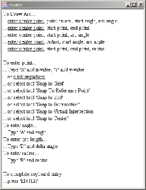
Using eGuide
An interactive help facility can be invoked with the 'eGuide...' command in the 'Help' menu.
eGuide tracks you as you draw and tries to give hints on what to do next. As at any given time there are a ziljon actions you can take the eGuide cannot
give you step by step instructions. The hints are given in a computer generated artificial stupidity Finglish language,
my appologies to any language puritans.
To give help on help is difficult but broadly speaking the eGuide works as follows. Based on the selected drawing (or editing)
tool the various ways on how you can draw (or edit) are described in the eGuide window. The underlined items indicate what input (such as points,
lengths or dimensions) you have entered so far.
Below the help on how you can draw eGuide display what to do to input the required data into the system.
Common Mistakes aka Tips for the Day
Copying things
When copying, no copying takes place unless you specify a reference point. This is different from most Mac/PC
drawing programs and baffles newcomers. So to copy, first select the objects, then click the copy tool and lastly
click to enter a reference position.
Pasting Multiple with Rotate Each
Pasting multiple object is a powerfull way of creating many things. What confuses some is how each instance
(pasted copy of shapes) is rotated. To use this you need to check the 'Rotate Each' check box in the paste parameters
dialog, and type in into the 'Pre Rotate' entry field the orientation of the copied shape(s). To understand orientatio
imaging that you are about to draw a cart wheel. So you first draw a single spoke. If you draw it up right (i.e. vertical, with
the hub at bottom) then you enter 90 degrees into the pre-rotate field. When pasting the spoces (on an arc) you enter the center point,
the position of the first spoke and the position of the last spoke (or second spoke if you use the incremental mode). But if
you draw the first spoke (before you copy it) vertical (hub on the left) you enter 0 degrees for pre-rotation or (180 deg if the
you have the hub on the right side).
Zoom a Box
The zoom to a box command works in a one shot mode, you can only use it once without reselecting the command.
Aligning Back Ground Images
To allign a back ground image, go to the 'Tools/Back Ground Images...' dialog, select the image you want to allign
and click at the 'Reposition Image' button. The dialog closes and now you enter (click) four points. With the first
two points you specify two points in the background image that you want to align with the two last points you enter.
The back ground image is so scaled, rotated and translated that the 1st/3rd and 2nd/4th points co-incide.
Writing Text at Angle
To write text at angle, you need to first enter the angle and then the position. So type 'A' for angle, type in the angle and
then click at the position.
Dimensioning Shapes
The default snap tool for dimensioning is snap to a point. This is propably not what you want. So you need to click at the
'pick shape' tool and then click at the shape you want to dimension.
Using the Enter Key
Some entry fields REQUIRE you to complete the entry with the ENTER key, otherwise the value is ignored. This is confusing
if you enter a value in a dialog, and click OK and the value you just entered is ignored.
On the other hand, when using the numeric entry entry fields (at the bottom of the main window) you must not press
ENTER until you have filled in all the fields you want to fill. So type something like 'X123Y456A78' and then press ENTER.
Printing
Printing is pretty straight forward, except that you need to understand the printable area concept.
Because drawings frequently are larger than what fits on a single page, jDraft
prints as many pages as necessary. The paper size
('Settings/Document Size...') is supposed to align with the real physical paper. However, if you use e.g. A4 (210 x 297 mm) as the
paper size
most printers cannot print that area. This is annoying as it means that four pages will be printed if you try to print
one page. The answer to this problem is to set the printable area to a slightly smaller area than the real paper. For example
if your drawing is A3 size (420 x 297 mm2) set the printable area to (5,5,419,287) and most printers will print only two pages
(or better yet, if you have A3 printer, only one page). Of course you must take care not to draw outside the printable area.
Keyboard Short Cuts
The following keyboard short cuts are available. Note that sometimes it appears as if they did not work. This is because
the drawing view does not have the keyboard focus. In that case you need to click at the drawing area. You may not like
all keys chosen for the short-cuts but these are what are available after the look&feels have taken their share; hence the
need to use the SHIFT key at times.
| ENTER | Same as clicking the ENTER button |
| HOME | Zoom to seleciont |
| PAGE UP | Zoom iut |
| PAGE DOWN | Zoom in |
| SHIFT LEFT | Scroll left |
| SHIFT RIGHT | Srocll right |
| SHIFT UP | Scroll up |
| SHIFT DOWN | Scroll down |
| END | Zoom 100% |
| DELETE | Same as right clicking and choosing DELETE |
| CTRL CLICK | Sets the last point for numeric entry |
| SHIFT | Forces vertical/horizontal drawing |
Note that the zoom/scroll controls operate on the last clicked view if you have multplie view panes.


