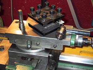
This picture shows the top slide of my lathe with toolpost removed. To be able to mill, I must get the necessary x-y-z movements relative to the chuck, and this is not possible with this setup.
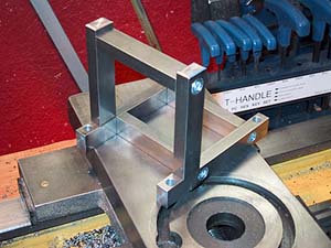 So, how to do it? By changing the top slide to a vertical slide - I accomplished that by making a sturdy angle bracket of 10x16mm "key stock". I won't give any dimensions, since lathes do vary in size, but you get the idea from the pictures. I drilled and tapped the pieces so that I could bolt them together before hard soldering, checking that they were correctly aligned with a precision ground 90° square.
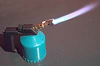
I used two (one was not enough) gas burners of this type to heat up the material to the required red heat for the silver solder. This burner (brand "Providus") uses disposable (190 gram) gas containers that costs around one US dollar apiece - the entire burner costs only 15 $, so I bought three... And they have piezo electric ignition, too!

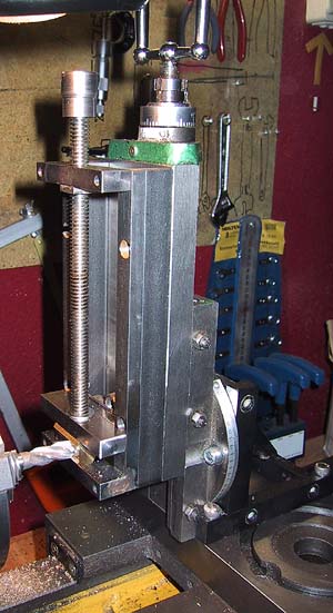
Here you can see the finished angle bracket mounted on the cross slide (I drilled and tapped four M6 holes in the cross slide for it), and the top slide mounted vertically onto the bracket. Note the silver soldered diagonal brace - it is absolutely necessary to ensure rigidity.
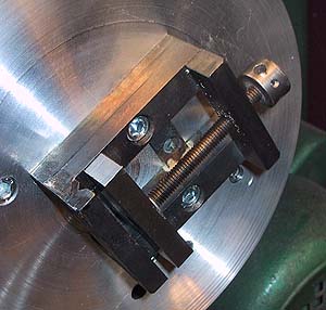
 Next, a vise to attach to the vertical slide - again, made of key stock (what else... ;-). I made the vise as long as the slide, so I can clamp rather large pieces in it. The tightening screw is 10mm dia, 2mm pitch trapezoidal thread - I happened to have a piece left over from 1984, when I built my computerized animation camera stand - see my ANIMATO page for details about that. I sunk in (halfways) and silver soldered a nut into the rear end. The trapeze thread gives nice tightening action. The knob has a through hole, for a removable handle. The holes you see in the "rails" are for fastening the vise to the slide with four M6 screws - countersunk, so they do not interfere with the clamp.
 The "rails" of the vise and the sliding clamp are designed like this - seen from the back end. Note the shim at the arrow - this allows the clamp to slide freely over the side rails. The four "corners" of the vise "frame" are M6 bolted, and then silver soldered to exactly 90°. Using key stock in suitable dimensions enabled me to build this vise in just a couple of hours. In fact, designing this webpage took me longer...
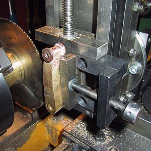
 Here you can see the vertical slide and the new vise in operation - i.e. milling on the lathe.
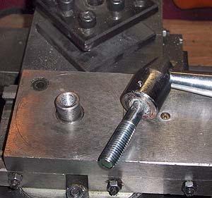 In order to fit the vise to the top slide, I had to modify the toolpost tightening screw and clamp to clear the vise - now, the screw is attached to the handle, and the nut is in the slide - protruding a bit, but not so much as to interfere with the vise. Compare with the picture on top of this page!
 I had made a similar, smaller (60 x 80 mm) vise a couple of years ago for my Unimat, and this has proven to be excellent for holding small objects on the new, large lathe's faceplate (also homemade, I turned it out of a piece of 10mm thick aluminum, and drill & tap new M6 fastening holes in it when necessary).
 Here's a "double-header": A vise in a vise! With this setup I was able to split a block for link hanger arms in two - impossible to do lengthwise due to the small saw diameter.
 Here's a funny thing: A box of honing stones, made in China. I wonder if the brand name "Intensive-Labour" on the label refers to what I'm supposed to do, or what those Chinese workers already have done... ;-)