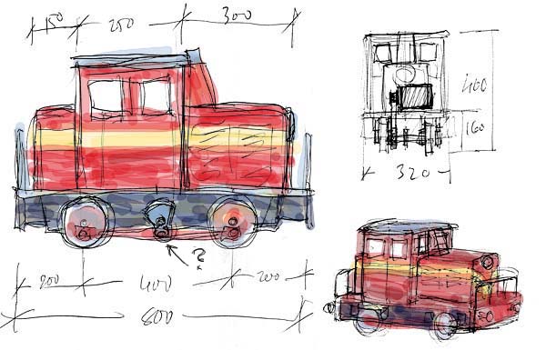
This is what I intend to build, in a very short time: a little "diesel" switcher, battery operated.
Everything will be made from scrounged and scrap materials, or stuff that I already have on hand. Except for a couple of 12 volt 60 Ah car batteries for power and weight, I hopefully need not buy anything...
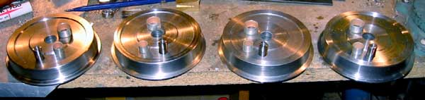
In fact, I've already turned the wheels out of solid 5" bar stock (I had a few slices that I used for the forming of the 3003's boiler tube plates), and have made the axle boxes (with PTFE-coated steel bearing inserts, also left over from the 3003 project), and started on the frame - that's some of the key stock I had in stock.
Wheels with coupling pins, and their bearings.
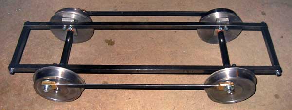
The frame with axleboxes. I haven't yet decided whether I'll drive the coupling rods from a third, counter-balanced axle, or from one of the main axles, leaving out the middle axle in the drawing - however, I think it might be visually nice to have it there, with the counterweight bobbing up and down when the loco is in motion...
As you can see below, the decision was made a few days later, after the successful hunting for a suitable drive motor:
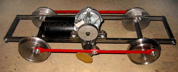
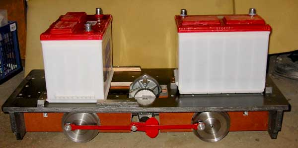
A friendly soul at a nearby bus depot donated a redundant windshield wiper motor (24 volts) which eminently fit inside the frame. Note the added driving axle (with cosmetic "counterweights" of brass, still unpainted) - the power is actually transmitted to the wheels via the coupling rods, just like in real life... The wheels are now quartered, attached to the axles with Loctite 603. The driving axle has ball bearings, and since the driving cranks are attached with grub screws, these parts can easily be removed if necessary.
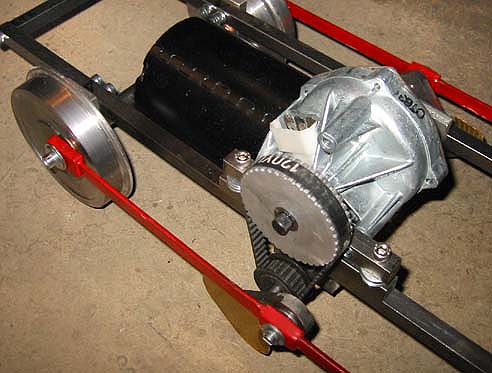
The motor runs rather slowly, but with a step-up factor of 2.2, administered with a couple of toothed pulleys (40 and 18 teeth) and corresponding belt, the loco will run at two speeds (just as windshield wipers ;-), 1.5 and 3 mph respectively - safe speeds to let 5 year old kids of friends and relatives run the train by themselves...
The motor draws about two amps at 24 volts when there is no load on the wheels, and will draw quite a bit more in operation - braking an axle by hand, my electronic power supply maxed out at a little over 4 amps, but the wheels still didn't stall, just slowed down a bit. On battery power, the available current will certainly be high enough for running at full speed!
I can change the transmission ratio by changing the pulleys, if I ever need the loco to run any faster - tensioning of the belt is done simply, just by shimming up the motor's mounting bracket with washers (I may improve this to an adjustable design later...)
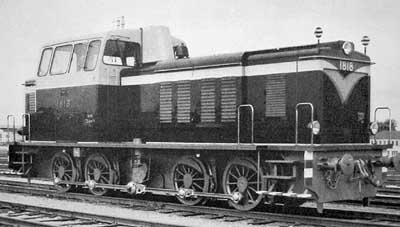
This, by the way, is my "prototype" - the sketch above was just from memory, but I finally found a picture of the loco in an old book. As you can see, my memory of the coloration was incorrect - the cab top is yellow, not red!
I won't adhere to this too precisely - as you've noticed, I'm making a shorter version of it, with just two axles instead of four, and much simplified.
I'm just curious to see how quickly I can put a working loco together, which is also pleasing to the eye...
Easter is here! Most of my woodworking tools are in Hangö, where I spend the holidays... So, time for some loco work again!
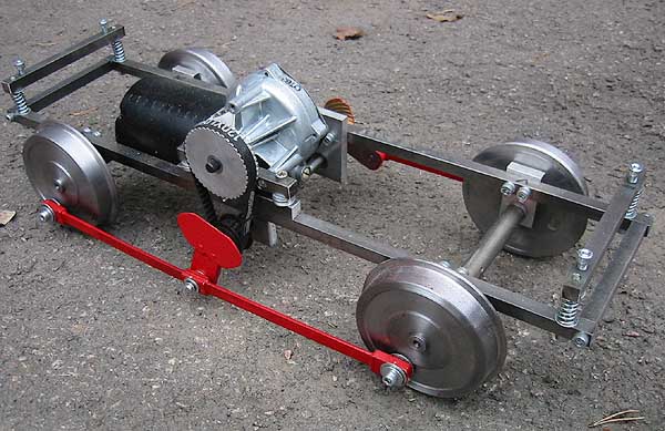
The spring rigging is extremely simple: one spring in each corner will keep the heavy top structure (containing the two car batteries) from getting too hard jars, it will "float" on the springs. The frame itself is springy enough to take care of the wheels on the track - as can be seen, there is no springing in the axleboxes, they're bolted to the frame.
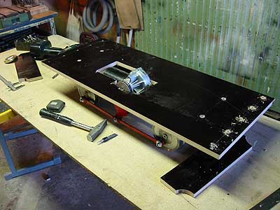
The superstructure is built up on a 15 mm (5/8") thick piece of a special kind of weatherproof plywood, laminated with phenolic resin. I used this material for the cab and cars of my steam loco, too.
As can be seen, I had to cut out a recess for the motor in the base...
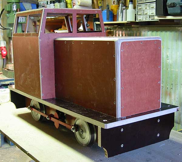
Four hours later - now this starts to resemble something! The entire top can be lifted off for access to batteries and motor.
As seen in this image, I've rounded the edges of the front and rear "covers". After shooting this picture I spread some filler over the screwheads and sanded the whole thing. The plywood's resin surface won't take paint very well unless it is first sanded matt.
The two batteries. The front one just barely fits inside the hood! Heavy stuff - they will provide good traction!
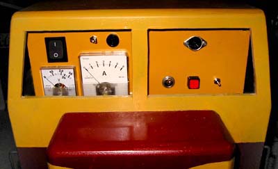
I rummaged through my scrap boxes and found a couple of old panel meters and several suitable switches. With these, I put together a control panel accessible through the rear windows of the cab.
The meters will help monitoring the voltage and current of the batteries, during running as well as charging. The voltmeter is adjusted with a series resistor for a max display of 30 volts, with a mark at the nominal 24.
The motor draws a little over 5 amps when strongly braked (but not stalled - that is a lot higher), so I shunted the ammeter for a maximum display of 6 amps - that should be enough for both normal running and charging. If not, I'll change the shunt and make another scale...
Above the ammeter is a fuse holder, with a 16 Amp fuse, just for safety, in case of a short circuit. The three switches in the right side window are forward/reverse, horn, and half/full speed, respectively. The socket above the switches will take the remote control's cable plug, and will also be used for charging the batteries - overnight, at about 5 amps only, so no heavier connector is needed - especially since I connected 3 pins in parallell...
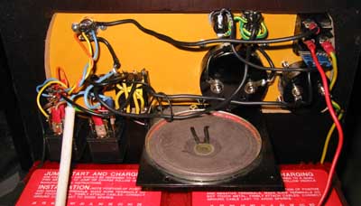
This is the back side of the panel. The loudspeaker serves as a horn for the loco, fed by a simple oscillator circuit I put together from components in my electronics scrap box: a "555" timer IC, a couple of resistors and a capacitor, soldered directly to the terminals under the speaker. A horn couldn't be much simpler!
The loco's exterior has also got a coat of paint and some simple railings. (The picture was taken before the installation of the control panel, so the cab looks a bit empty, here.)
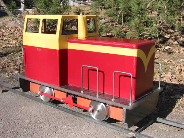
I started this project on March 30, 2003, with the idea to see how quickly it was possible to build a working 7 1/4" gauge locomotive. There is of course some cosmetic detailing work still missing, such as ventilation grills and headlights. But, since the loco can now be run on a track, it is virtually finished.
At this writing, I've used 11 afternoons or evenings (whenever I've had the spare time), altogether about 45 hours. It's now April 27th. Thats less than a month from the start to, well, at least some kind of a finish...
A quickie, indeed!
An important note:
The toothed belt drive shown above did not stand up to the high forces involved - the belt snapped after just a short time of use. I have re-designed the drive, removing the worm reduction drive from the motor as well as the belt pulleys, and substituted two gears instead, 12 and 100 teeth, respectively. This also gives a better transmission ratio (1:8,33, which gives a higher speed), and still the power of the motor suffices to pull the loco and two cars, even carrying two adults up the 4% grade of my track.
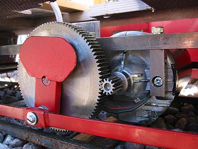
I had to drop the motor (now mounted crosswise) below the frame to get everything to fit. I'll still have to paint the gear black, so that the loco doesn't look like a 0-6-0 on one side, and a 0-4-0 on the other... ;-)
The power consumption is amazingly low, on level track the motor needs only 2 amps (at 24 volts), and no more than 8 to 10 amps with a full load of one adult and two kids on the 4% grade. On the downgrade the ammeter needle dropped to zero!
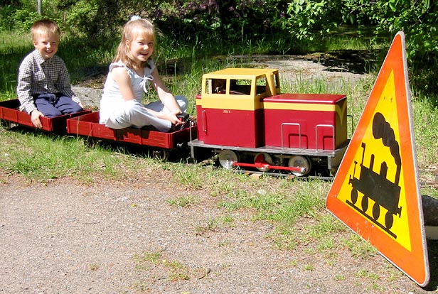
Here's a picture of my cousin's kids running the train all by themselves. We had a birthday garden-party with some 30 guests, half of them kids. The little loco ran non-stop all day, with just a couple of pauses while I ran the 3003 on steam...
A couple of seats in the low-sided cars make the ride safe for small as well as somewhat larger kids...
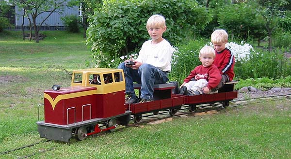
Chrisse, my innovative friend, seems to be trying out "101 positions to enjoy a Quickie" :
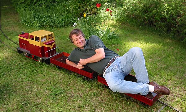
... and from the look on his face, I think he does... ;-)
For a look at another builder's "Quicker than Quickie", have a look HERE!
Close this window when you are ready...
Any information presented on this website (especially any do-it-yourself instructions) is given without any acceptance of liability for damage or injury - so, always remember: SAFETY FIRST!
The material on this page and its related pages is Copyright © 2001-2007 by J-E Nystrom. You may NOT copy, transmit and/or publish any of my images or texts in print, electronically, on your own website or in any other way. The author retains all rights to this work, with this sole exception: Storing the pages on your own computer or printing out a paper copy, for your own, strictly personal use is allowed.
You may, however, freely link to the "Building Live Steam Locomotives" page at: http://www.saunalahti.fi/animato/steam, or to my Animation Home Page at: http://www.saunalahti.fi/animato. You should NOT link directly to THIS page, since it's address may change in the future. Also, you may not put any of these pages or pictures into "frames" on your own website.
Thank you.