.... is really the "signature" of the steam locomotive. You can directly see if it's a wood or coal burner: woodburners always have a large, conical "balloon" stack, containing some form of spark extiguisher, while coal burners usually have straight, narrow stacks.
The 3003 originally had the patented "Radley/Hunter" stack (left), containing a stationary fan-like structure that caused the smoke gases to whirl around inside the stack. This flung the cinders towards the outer side of a perforated, cylindrical inner part of the stack, where the sparks were disintegrated, extinguished and collected as ash in the lower part of the stack.
I'm not building the entire spark arrestor system - not necessary, since I intend to burn propane, not wood... It's only important that the stack looks like the original on the outside, so I can leave out most of the interior details.
Laying out the parts was easy - using the original 1875 drawing, I measured the upper and lower diameter as well as the sides of each cone. Calculating distances from the imagined "point" of the cone, it was a piece of cake, or rather "pi", to get the angle of the sector needed to from the cone.
The drawing shows all the parts necessary to make the stack - excluding an inner cone and tube, which will connect to the "petticoat cone" inside the smokebox.
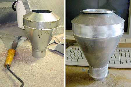
Using an inner tube (which will isolate the rest of the stack from the heat of the smoke gases) enabled me to use soft solder in the construction of the stack - I did keep the different parts together with a few pop rivets during assembly, but the rivets were later removed. Keeping the stack cool will also ensure that the paint won't flake off...
The parts are galvanized iron - roofing materail, in fact - this proved to be sturdy enough. The base ring that attaches the stack to the smoke box is still to be made of much thicker brass, turned to size, and riveted or bolted to the "E"-marked tube of the stack.
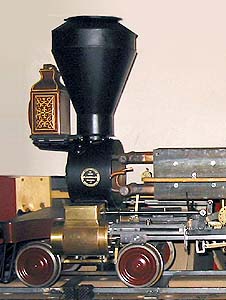
The stack in its proper place, painted with just a coat of heat-resistant primer. Note that the "boiler", i.e. heat exchanger, is already in position. The valves and steam and water connections, and the insulating envelope for the boiler are all still missing, however.
Close this window when you are ready...
Any information presented on this website (especially any do-it-yourself instructions) is given without any acceptance of liability for damage or injury - so, always remember: SAFETY FIRST!
The material on this page and its related pages is Copyright © 2001-2007 by J-E Nystrom. You may NOT copy, transmit and/or publish any of my images or texts in print, electronically, on your own website or in any other way. The author retains all rights to this work, with this sole exception: Storing the pages on your own computer or printing out a paper copy, for your own, strictly personal use is allowed.
You may, however, freely link to the "Building Live Steam Locomotives" page at: http://www.saunalahti.fi/animato/steam, or to my Animation Home Page at: http://www.saunalahti.fi/animato. You should NOT link directly to THIS page, since it's address may change in the future. Also, you may not put any of these pages or pictures into "frames" on your own website.
Thank you.